TGSI
TGSI, Tungsten Graphics Shader Infrastructure, is an intermediate language for describing shaders. Since Gallium is inherently shaderful, shaders are an important part of the API. TGSI is the only intermediate representation used by all drivers.
Basics
All TGSI instructions, known as opcodes, operate on arbitrary-precision floating-point four-component vectors. An opcode may have up to one destination register, known as dst, and between zero and three source registers, called src0 through src2, or simply src if there is only one.
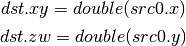
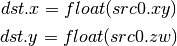
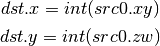
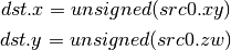
Some instructions, like I2F, permit re-interpretation of vector components as integers. Other instructions permit using registers as two-component vectors with double precision; see Double ISA.
When an instruction has a scalar result, the result is usually copied into each of the components of dst. When this happens, the result is said to be replicated to dst. RCP is one such instruction.
Modifiers
TGSI supports modifiers on inputs (as well as saturate modifier on instructions).
For inputs which have a floating point type, both absolute value and negation modifiers are supported (with absolute value being applied first). TGSI_OPCODE_MOV is considered to have float input type for applying modifiers.
For inputs which have signed or unsigned type only the negate modifier is supported.
Instruction Set
Core ISA
These opcodes are guaranteed to be available regardless of the driver being used.
- ARL (Address Register Load)
- MOV (Move)
- LIT (Light Coefficients)
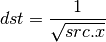
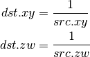
- RCP (Reciprocal)
This instruction replicates its result.

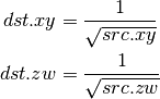
- RSQ (Reciprocal Square Root)
This instruction replicates its result. The results are undefined for src <= 0.
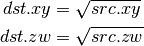
- SQRT (Square Root)
This instruction replicates its result. The results are undefined for src < 0.
- EXP (Approximate Exponential Base 2)
- LOG (Approximate Logarithm Base 2)
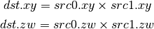
- MUL (Multiply)
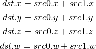
- ADD (Add)
- DP3 (3-component Dot Product)
This instruction replicates its result.

- DP4 (4-component Dot Product)
This instruction replicates its result.

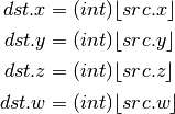
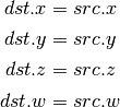
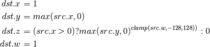
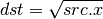
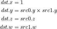
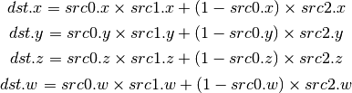
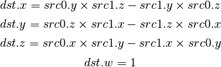
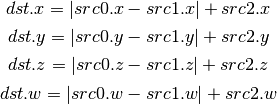
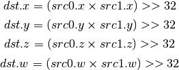
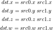
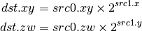
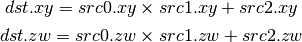
- DST (Distance Vector)
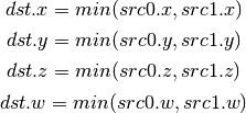
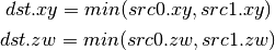
- MIN (Minimum)
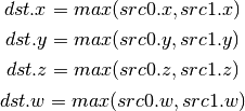
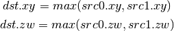
- MAX (Maximum)
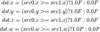
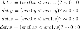
- SLT (Set On Less Than)
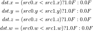
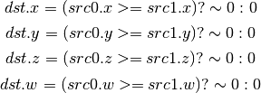
- SGE (Set On Greater Equal Than)
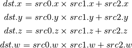
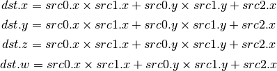
- MAD (Multiply And Add)
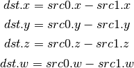
- SUB (Subtract)
- LRP (Linear Interpolate)
- DP2A (2-component Dot Product And Add)
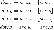
- FRC (Fraction)
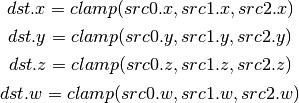
- CLAMP (Clamp)
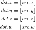
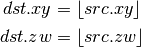
- FLR (Floor)
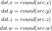
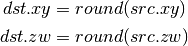
- ROUND (Round)
- EX2 (Exponential Base 2)
This instruction replicates its result.

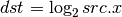
- LG2 (Logarithm Base 2)
This instruction replicates its result.
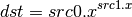
- POW (Power)
This instruction replicates its result.
- XPD (Cross Product)
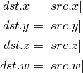
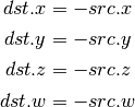
- ABS (Absolute)
- DPH (Homogeneous Dot Product)
This instruction replicates its result.

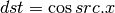
- COS (Cosine)
This instruction replicates its result.
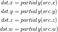
- DDX, DDX_FINE (Derivative Relative To X)
The fine variant is only used when PIPE_CAP_TGSI_FS_FINE_DERIVATIVE is advertised. When it is, the fine version guarantees one derivative per row while DDX is allowed to be the same for the entire 2x2 quad.
- DDY, DDY_FINE (Derivative Relative To Y)
The fine variant is only used when PIPE_CAP_TGSI_FS_FINE_DERIVATIVE is advertised. When it is, the fine version guarantees one derivative per column while DDY is allowed to be the same for the entire 2x2 quad.
- PK2H (Pack Two 16-bit Floats)
TBD
- PK2US (Pack Two Unsigned 16-bit Scalars)
TBD
- PK4B (Pack Four Signed 8-bit Scalars)
TBD
- PK4UB (Pack Four Unsigned 8-bit Scalars)
TBD
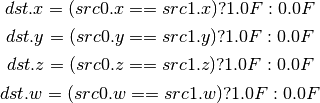
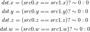
- SEQ (Set On Equal)
- SGT (Set On Greater Than)

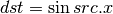
- SIN (Sine)
This instruction replicates its result.
- SLE (Set On Less Equal Than)

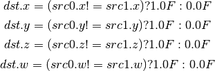
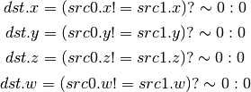
- SNE (Set On Not Equal)
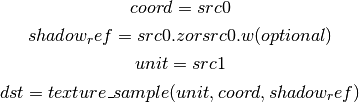
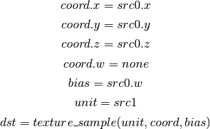
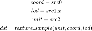
- TEX (Texture Lookup)
for array textures src0.y contains the slice for 1D, and src0.z contain the slice for 2D.
for shadow textures with no arrays (and not cube map), src0.z contains the reference value.
for shadow textures with arrays, src0.z contains the reference value for 1D arrays, and src0.w contains the reference value for 2D arrays and cube maps.
for cube map array shadow textures, the reference value cannot be passed in src0.w, and TEX2 must be used instead.
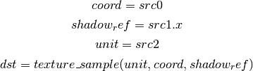
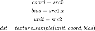
- TEX2 (Texture Lookup (for shadow cube map arrays only))
this is the same as TEX, but uses another reg to encode the reference value.
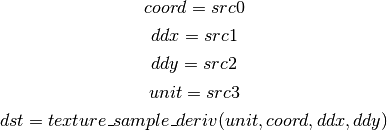
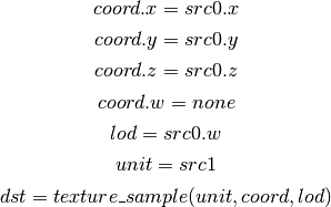
- TXD (Texture Lookup with Derivatives)
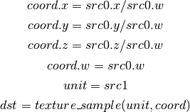
- TXP (Projective Texture Lookup)
- UP2H (Unpack Two 16-Bit Floats)
TBD
Note
Considered for removal.
- UP2US (Unpack Two Unsigned 16-Bit Scalars)
TBD
Note
Considered for removal.
- UP4B (Unpack Four Signed 8-Bit Values)
TBD
Note
Considered for removal.
- UP4UB (Unpack Four Unsigned 8-Bit Scalars)
TBD
Note
Considered for removal.
- ARR (Address Register Load With Round)
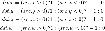
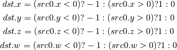
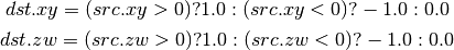
- SSG (Set Sign)
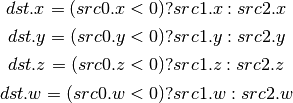
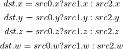
- CMP (Compare)
- KILL_IF (Conditional Discard)
Conditional discard. Allowed in fragment shaders only.

- KILL (Discard)
Unconditional discard. Allowed in fragment shaders only.
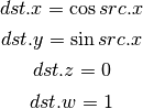
- SCS (Sine Cosine)
- TXB (Texture Lookup With Bias)
for cube map array textures and shadow cube maps, the bias value cannot be passed in src0.w, and TXB2 must be used instead.
if the target is a shadow texture, the reference value is always in src.z (this prevents shadow 3d and shadow 2d arrays from using this instruction, but this is not needed).
- TXB2 (Texture Lookup With Bias (some cube maps only))
this is the same as TXB, but uses another reg to encode the lod bias value for cube map arrays and shadow cube maps. Presumably shadow 2d arrays and shadow 3d targets could use this encoding too, but this is not legal.
shadow cube map arrays are neither possible nor required.
- DIV (Divide)
- DP2 (2-component Dot Product)
This instruction replicates its result.

- TXL (Texture Lookup With explicit LOD)
for cube map array textures, the explicit lod value cannot be passed in src0.w, and TXL2 must be used instead.
if the target is a shadow texture, the reference value is always in src.z (this prevents shadow 3d / 2d array / cube targets from using this instruction, but this is not needed).
- TXL2 (Texture Lookup With explicit LOD (for cube map arrays only))
this is the same as TXL, but uses another reg to encode the explicit lod value. Presumably shadow 3d / 2d array / cube targets could use this encoding too, but this is not legal.
shadow cube map arrays are neither possible nor required.
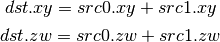
- PUSHA (Push Address Register On Stack)
push(src.x) push(src.y) push(src.z) push(src.w)
Note
Considered for cleanup.
Note
Considered for removal.
- POPA (Pop Address Register From Stack)
dst.w = pop() dst.z = pop() dst.y = pop() dst.x = pop()
Note
Considered for cleanup.
Note
Considered for removal.
- CALLNZ (Subroutine Call If Not Zero)
TBD
Note
Considered for cleanup.
Note
Considered for removal.
Compute ISA
These opcodes are primarily provided for special-use computational shaders. Support for these opcodes indicated by a special pipe capability bit (TBD).
XXX doesn’t look like most of the opcodes really belong here.
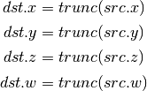
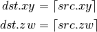
- CEIL (Ceiling)
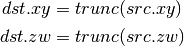
- TRUNC (Truncate)
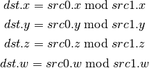
- MOD (Modulus)
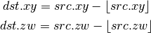
- UARL (Integer Address Register Load)
Moves the contents of the source register, assumed to be an integer, into the destination register, which is assumed to be an address (ADDR) register.
- SAD (Sum Of Absolute Differences)
- TXF (Texel Fetch)
As per NV_gpu_shader4, extract a single texel from a specified texture image. The source sampler may not be a CUBE or SHADOW. src 0 is a four-component signed integer vector used to identify the single texel accessed. 3 components + level. Just like texture instructions, an optional offset vector is provided, which is subject to various driver restrictions (regarding range, source of offsets). TXF(uint_vec coord, int_vec offset).
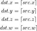
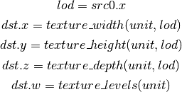
- TXQ (Texture Size Query)
As per NV_gpu_program4, retrieve the dimensions of the texture depending on the target. For 1D (width), 2D/RECT/CUBE (width, height), 3D (width, height, depth), 1D array (width, layers), 2D array (width, height, layers). Also return the number of accessible levels (last_level - first_level + 1) in W.
For components which don’t return a resource dimension, their value is undefined.
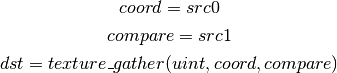
- TG4 (Texture Gather)
As per ARB_texture_gather, gathers the four texels to be used in a bi-linear filtering operation and packs them into a single register. Only works with 2D, 2D array, cubemaps, and cubemaps arrays. For 2D textures, only the addressing modes of the sampler and the top level of any mip pyramid are used. Set W to zero. It behaves like the TEX instruction, but a filtered sample is not generated. The four samples that contribute to filtering are placed into xyzw in clockwise order, starting with the (u,v) texture coordinate delta at the following locations (-, +), (+, +), (+, -), (-, -), where the magnitude of the deltas are half a texel.
PIPE_CAP_TEXTURE_SM5 enhances this instruction to support shadow per-sample depth compares, single component selection, and a non-constant offset. It doesn’t allow support for the GL independent offset to get i0,j0. This would require another CAP is hw can do it natively. For now we lower that before TGSI.
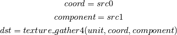
(with SM5 - cube array shadow)
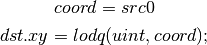
- LODQ (level of detail query)
Compute the LOD information that the texture pipe would use to access the texture. The Y component contains the computed LOD lambda_prime. The X component contains the LOD that will be accessed, based on min/max lod’s and mipmap filters.
Integer ISA
These opcodes are used for integer operations. Support for these opcodes indicated by PIPE_SHADER_CAP_INTEGERS (all of them?)
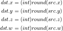
- I2F (Signed Integer To Float)
Rounding is unspecified (round to nearest even suggested).
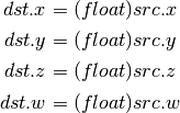
- U2F (Unsigned Integer To Float)
Rounding is unspecified (round to nearest even suggested).
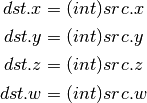
- F2I (Float to Signed Integer)
Rounding is towards zero (truncate). Values outside signed range (including NaNs) produce undefined results.
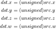
- F2U (Float to Unsigned Integer)
Rounding is towards zero (truncate). Values outside unsigned range (including NaNs) produce undefined results.
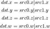
- UADD (Integer Add)
This instruction works the same for signed and unsigned integers. The low 32bit of the result is returned.
- UMAD (Integer Multiply And Add)
This instruction works the same for signed and unsigned integers. The multiplication returns the low 32bit (as does the result itself).
- UMUL (Integer Multiply)
This instruction works the same for signed and unsigned integers. The low 32bit of the result is returned.
- IMUL_HI (Signed Integer Multiply High Bits)
The high 32bits of the multiplication of 2 signed integers are returned.
- UMUL_HI (Unsigned Integer Multiply High Bits)
The high 32bits of the multiplication of 2 unsigned integers are returned.
- IDIV (Signed Integer Division)
TBD: behavior for division by zero.
- UDIV (Unsigned Integer Division)
For division by zero, 0xffffffff is returned.
- UMOD (Unsigned Integer Remainder)
If second arg is zero, 0xffffffff is returned.
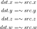
- NOT (Bitwise Not)
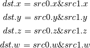
- AND (Bitwise And)
- OR (Bitwise Or)
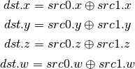
- XOR (Bitwise Xor)
- IMAX (Maximum of Signed Integers)
- UMAX (Maximum of Unsigned Integers)
- IMIN (Minimum of Signed Integers)
- UMIN (Minimum of Unsigned Integers)
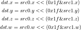
- SHL (Shift Left)
The shift count is masked with 0x1f before the shift is applied.
- ISHR (Arithmetic Shift Right (of Signed Integer))
The shift count is masked with 0x1f before the shift is applied.

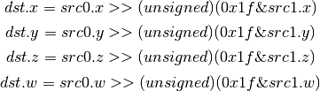
- USHR (Logical Shift Right)
The shift count is masked with 0x1f before the shift is applied.
- UCMP (Integer Conditional Move)
- ISSG (Integer Set Sign)
- FSLT (Float Set On Less Than (ordered))
Same comparison as SLT but returns integer instead of 1.0/0.0 float
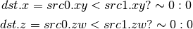
- ISLT (Signed Integer Set On Less Than)
- USLT (Unsigned Integer Set On Less Than)
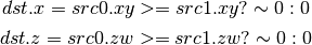
- FSGE (Float Set On Greater Equal Than (ordered))
Same comparison as SGE but returns integer instead of 1.0/0.0 float
- ISGE (Signed Integer Set On Greater Equal Than)
- USGE (Unsigned Integer Set On Greater Equal Than)
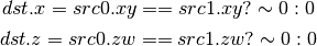
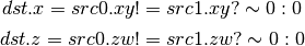
- FSEQ (Float Set On Equal (ordered))
Same comparison as SEQ but returns integer instead of 1.0/0.0 float
- USEQ (Integer Set On Equal)
- FSNE (Float Set On Not Equal (unordered))
Same comparison as SNE but returns integer instead of 1.0/0.0 float
- USNE (Integer Set On Not Equal)
- INEG (Integer Negate)
Two’s complement.
- IABS (Integer Absolute Value)
Bitwise ISA
These opcodes are used for bit-level manipulation of integers.
- IBFE (Signed Bitfield Extract)
See SM5 instruction of the same name. Extracts a set of bits from the input, and sign-extends them if the high bit of the extracted window is set.
Pseudocode:
def ibfe(value, offset, bits):
  offset = offset & 0x1f
  bits = bits & 0x1f
  if bits == 0: return 0
  # Note: >> sign-extends
  if width + offset < 32:
    return (value << (32 - offset - bits)) >> (32 - bits)
  else:
    return value >> offset
- UBFE (Unsigned Bitfield Extract)
See SM5 instruction of the same name. Extracts a set of bits from the input, without any sign-extension.
Pseudocode:
def ubfe(value, offset, bits):
  offset = offset & 0x1f
  bits = bits & 0x1f
  if bits == 0: return 0
  # Note: >> does not sign-extend
  if width + offset < 32:
    return (value << (32 - offset - bits)) >> (32 - bits)
  else:
    return value >> offset
- BFI (Bitfield Insert)
See SM5 instruction of the same name. Replaces a bit region of ‘base’ with the low bits of ‘insert’.
Pseudocode:
def bfi(base, insert, offset, bits):
  offset = offset & 0x1f
  bits = bits & 0x1f
  mask = ((1 << bits) - 1) << offset
  return ((insert << offset) & mask) | (base & ~mask)
- BREV (Bitfield Reverse)
See SM5 instruction BFREV. Reverses the bits of the argument.
- POPC (Population Count)
See SM5 instruction COUNTBITS. Counts the number of set bits in the argument.
- LSB (Index of lowest set bit)
See SM5 instruction FIRSTBIT_LO. Computes the 0-based index of the first set bit of the argument. Returns -1 if none are set.
- IMSB (Index of highest non-sign bit)
See SM5 instruction FIRSTBIT_SHI. Computes the 0-based index of the highest non-sign bit of the argument (i.e. highest 0 bit for negative numbers, highest 1 bit for positive numbers). Returns -1 if all bits are the same (i.e. for inputs 0 and -1).
- UMSB (Index of highest set bit)
See SM5 instruction FIRSTBIT_HI. Computes the 0-based index of the highest set bit of the argument. Returns -1 if none are set.
Geometry ISA
These opcodes are only supported in geometry shaders; they have no meaning in any other type of shader.
- EMIT (Emit)
Generate a new vertex for the current primitive into the specified vertex stream using the values in the output registers.
- ENDPRIM (End Primitive)
Complete the current primitive in the specified vertex stream (consisting of the emitted vertices), and start a new one.
GLSL ISA
These opcodes are part of GLSL‘s opcode set. Support for these opcodes is determined by a special capability bit, GLSL. Some require glsl version 1.30 (UIF/BREAKC/SWITCH/CASE/DEFAULT/ENDSWITCH).
- CAL (Subroutine Call)
push(pc) pc = target
- RET (Subroutine Call Return)
pc = pop()
- CONT (Continue)
Unconditionally moves the point of execution to the instruction after the last bgnloop. The instruction must appear within a bgnloop/endloop.
Note
Support for CONT is determined by a special capability bit, TGSI_CONT_SUPPORTED. See Screen for more information.
- BGNLOOP (Begin a Loop)
Start a loop. Must have a matching endloop.
- BGNSUB (Begin Subroutine)
Starts definition of a subroutine. Must have a matching endsub.
- ENDLOOP (End a Loop)
End a loop started with bgnloop.
- ENDSUB (End Subroutine)
Ends definition of a subroutine.
- NOP (No Operation)
Do nothing.
- BRK (Break)
Unconditionally moves the point of execution to the instruction after the next endloop or endswitch. The instruction must appear within a loop/endloop or switch/endswitch.
- BREAKC (Break Conditional)
Conditionally moves the point of execution to the instruction after the next endloop or endswitch. The instruction must appear within a loop/endloop or switch/endswitch. Condition evaluates to true if src0.x != 0 where src0.x is interpreted as an integer register.
Note
Considered for removal as it’s quite inconsistent wrt other opcodes (could emulate with UIF/BRK/ENDIF).
- IF (Float If)
Start an IF ... ELSE .. ENDIF block. Condition evaluates to true if
src0.x != 0.0where src0.x is interpreted as a floating point register.
- UIF (Bitwise If)
Start an UIF ... ELSE .. ENDIF block. Condition evaluates to true if
src0.x != 0where src0.x is interpreted as an integer register.
- ELSE (Else)
Starts an else block, after an IF or UIF statement.
- ENDIF (End If)
Ends an IF or UIF block.
- SWITCH (Switch)
Starts a C-style switch expression. The switch consists of one or multiple CASE statements, and at most one DEFAULT statement. Execution of a statement ends when a BRK is hit, but just like in C falling through to other cases without a break is allowed. Similarly, DEFAULT label is allowed anywhere not just as last statement, and fallthrough is allowed into/from it. CASE src arguments are evaluated at bit level against the SWITCH src argument.
Example:
SWITCH src[0].x
CASE src[0].x
(some instructions here)
(optional BRK here)
DEFAULT
(some instructions here)
(optional BRK here)
CASE src[0].x
(some instructions here)
(optional BRK here)
ENDSWITCH
- CASE (Switch case)
This represents a switch case label. The src arg must be an integer immediate.
- DEFAULT (Switch default)
This represents the default case in the switch, which is taken if no other case matches.
- ENDSWITCH (End of switch)
Ends a switch expression.
Interpolation ISA
The interpolation instructions allow an input to be interpolated in a different way than its declaration. This corresponds to the GLSL 4.00 interpolateAt* functions. The first argument of each of these must come from TGSI_FILE_INPUT.
- INTERP_CENTROID (Interpolate at the centroid)
Interpolates the varying specified by src0 at the centroid
- INTERP_SAMPLE (Interpolate at the specified sample)
Interpolates the varying specified by src0 at the sample id specified by src1.x (interpreted as an integer)
- INTERP_OFFSET (Interpolate at the specified offset)
Interpolates the varying specified by src0 at the offset src1.xy from the pixel center (interpreted as floats)
Double ISA
The double-precision opcodes reinterpret four-component vectors into two-component vectors with doubled precision in each component.
- DADD (Add)
- DSEQ (Set on Equal)
- DSNE (Set on Equal)
- DSLT (Set on Less than)
- DSGE (Set on Greater equal)
- DFRAC (Fraction)
- DTRUNC (Truncate)
- DCEIL (Ceiling)
- DFLR (Floor)
- DROUND (Fraction)
- DSSG (Set Sign)
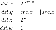
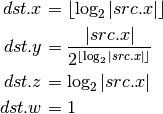
- DFRACEXP (Convert Number to Fractional and Integral Components)
Like the frexp() routine in many math libraries, this opcode stores the
exponent of its source to dst0, and the significand to dst1, such that
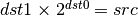 .
.
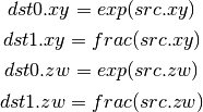
- DLDEXP (Multiply Number by Integral Power of 2)
This opcode is the inverse of DFRACEXP. The second source is an integer.
- DMIN (Minimum)
- DMAX (Maximum)
- DMUL (Multiply)
- DMAD (Multiply And Add)
- DRCP (Reciprocal)
- DSQRT (Square Root)
- DRSQ (Reciprocal Square Root)
- F2D (Float to Double)
- D2F (Double to Float)
- I2D (Int to Double)
- D2I (Double to Int)
- U2D (Unsigned Int to Double)
- D2U (Double to Unsigned Int)
Resource Sampling Opcodes
Those opcodes follow very closely semantics of the respective Direct3D instructions. If in doubt double check Direct3D documentation. Note that the swizzle on SVIEW (src1) determines texel swizzling after lookup.
- SAMPLE
Using provided address, sample data from the specified texture using the filtering mode identified by the gven sampler. The source data may come from any resource type other than buffers.
Syntax: SAMPLE dst, address, sampler_view, sampler
Example: SAMPLE TEMP[0], TEMP[1], SVIEW[0], SAMP[0]
- SAMPLE_I
Simplified alternative to the SAMPLE instruction. Using the provided integer address, SAMPLE_I fetches data from the specified sampler view without any filtering. The source data may come from any resource type other than CUBE.
Syntax: SAMPLE_I dst, address, sampler_view
Example: SAMPLE_I TEMP[0], TEMP[1], SVIEW[0]
The ‘address’ is specified as unsigned integers. If the ‘address’ is out of range [0...(# texels - 1)] the result of the fetch is always 0 in all components. As such the instruction doesn’t honor address wrap modes, in cases where that behavior is desirable ‘SAMPLE’ instruction should be used. address.w always provides an unsigned integer mipmap level. If the value is out of the range then the instruction always returns 0 in all components. address.yz are ignored for buffers and 1d textures. address.z is ignored for 1d texture arrays and 2d textures.
For 1D texture arrays address.y provides the array index (also as unsigned integer). If the value is out of the range of available array indices [0... (array size - 1)] then the opcode always returns 0 in all components. For 2D texture arrays address.z provides the array index, otherwise it exhibits the same behavior as in the case for 1D texture arrays. The exact semantics of the source address are presented in the table below:
resource type X Y Z W PIPE_BUFFER x ignored PIPE_TEXTURE_1D x mpl PIPE_TEXTURE_2D x y mpl PIPE_TEXTURE_3D x y z mpl PIPE_TEXTURE_RECT x y mpl PIPE_TEXTURE_CUBE not allowed as source PIPE_TEXTURE_1D_ARRAY x idx mpl PIPE_TEXTURE_2D_ARRAY x y idx mpl Where ‘mpl’ is a mipmap level and ‘idx’ is the array index.
- SAMPLE_I_MS
Just like SAMPLE_I but allows fetch data from multi-sampled surfaces.
Syntax: SAMPLE_I_MS dst, address, sampler_view, sample
- SAMPLE_B
Just like the SAMPLE instruction with the exception that an additional bias is applied to the level of detail computed as part of the instruction execution.
Syntax: SAMPLE_B dst, address, sampler_view, sampler, lod_bias
Example: SAMPLE_B TEMP[0], TEMP[1], SVIEW[0], SAMP[0], TEMP[2].x
- SAMPLE_C
Similar to the SAMPLE instruction but it performs a comparison filter. The operands to SAMPLE_C are identical to SAMPLE, except that there is an additional float32 operand, reference value, which must be a register with single-component, or a scalar literal. SAMPLE_C makes the hardware use the current samplers compare_func (in pipe_sampler_state) to compare reference value against the red component value for the surce resource at each texel that the currently configured texture filter covers based on the provided coordinates.
Syntax: SAMPLE_C dst, address, sampler_view.r, sampler, ref_value
Example: SAMPLE_C TEMP[0], TEMP[1], SVIEW[0].r, SAMP[0], TEMP[2].x
- SAMPLE_C_LZ
Same as SAMPLE_C, but LOD is 0 and derivatives are ignored. The LZ stands for level-zero.
Syntax: SAMPLE_C_LZ dst, address, sampler_view.r, sampler, ref_value
Example: SAMPLE_C_LZ TEMP[0], TEMP[1], SVIEW[0].r, SAMP[0], TEMP[2].x
- SAMPLE_D
SAMPLE_D is identical to the SAMPLE opcode except that the derivatives for the source address in the x direction and the y direction are provided by extra parameters.
Syntax: SAMPLE_D dst, address, sampler_view, sampler, der_x, der_y
Example: SAMPLE_D TEMP[0], TEMP[1], SVIEW[0], SAMP[0], TEMP[2], TEMP[3]
- SAMPLE_L
SAMPLE_L is identical to the SAMPLE opcode except that the LOD is provided directly as a scalar value, representing no anisotropy.
Syntax: SAMPLE_L dst, address, sampler_view, sampler, explicit_lod
Example: SAMPLE_L TEMP[0], TEMP[1], SVIEW[0], SAMP[0], TEMP[2].x
- GATHER4
Gathers the four texels to be used in a bi-linear filtering operation and packs them into a single register. Only works with 2D, 2D array, cubemaps, and cubemaps arrays. For 2D textures, only the addressing modes of the sampler and the top level of any mip pyramid are used. Set W to zero. It behaves like the SAMPLE instruction, but a filtered sample is not generated. The four samples that contribute to filtering are placed into xyzw in counter-clockwise order, starting with the (u,v) texture coordinate delta at the following locations (-, +), (+, +), (+, -), (-, -), where the magnitude of the deltas are half a texel.
- SVIEWINFO
Query the dimensions of a given sampler view. dst receives width, height, depth or array size and number of mipmap levels as int4. The dst can have a writemask which will specify what info is the caller interested in.
Syntax: SVIEWINFO dst, src_mip_level, sampler_view
Example: SVIEWINFO TEMP[0], TEMP[1].x, SVIEW[0]
src_mip_level is an unsigned integer scalar. If it’s out of range then returns 0 for width, height and depth/array size but the total number of mipmap is still returned correctly for the given sampler view. The returned width, height and depth values are for the mipmap level selected by the src_mip_level and are in the number of texels. For 1d texture array width is in dst.x, array size is in dst.y and dst.z is 0. The number of mipmaps is still in dst.w. In contrast to d3d10 resinfo, there’s no way in the tgsi instruction encoding to specify the return type (float/rcpfloat/uint), hence always using uint. Also, unlike the SAMPLE instructions, the swizzle on src1 resinfo allowing swizzling dst values is ignored (due to the interaction with rcpfloat modifier which requires some swizzle handling in the state tracker anyway).
- SAMPLE_POS
Query the position of a given sample. dst receives float4 (x, y, 0, 0) indicated where the sample is located. If the resource is not a multi-sample resource and not a render target, the result is 0.
- SAMPLE_INFO
dst receives number of samples in x. If the resource is not a multi-sample resource and not a render target, the result is 0.
Resource Access Opcodes
- LOAD (Fetch data from a shader resource)
Syntax: LOAD dst, resource, address
Example: LOAD TEMP[0], RES[0], TEMP[1]
Using the provided integer address, LOAD fetches data from the specified buffer or texture without any filtering.
The ‘address’ is specified as a vector of unsigned integers. If the ‘address’ is out of range the result is unspecified.
Only the first mipmap level of a resource can be read from using this instruction.
For 1D or 2D texture arrays, the array index is provided as an unsigned integer in address.y or address.z, respectively. address.yz are ignored for buffers and 1D textures. address.z is ignored for 1D texture arrays and 2D textures. address.w is always ignored.
- STORE (Write data to a shader resource)
Syntax: STORE resource, address, src
Example: STORE RES[0], TEMP[0], TEMP[1]
Using the provided integer address, STORE writes data to the specified buffer or texture.
The ‘address’ is specified as a vector of unsigned integers. If the ‘address’ is out of range the result is unspecified.
Only the first mipmap level of a resource can be written to using this instruction.
For 1D or 2D texture arrays, the array index is provided as an unsigned integer in address.y or address.z, respectively. address.yz are ignored for buffers and 1D textures. address.z is ignored for 1D texture arrays and 2D textures. address.w is always ignored.
Inter-thread synchronization opcodes
These opcodes are intended for communication between threads running within the same compute grid. For now they’re only valid in compute programs.
- MFENCE (Memory fence)
Syntax: MFENCE resource
Example: MFENCE RES[0]
This opcode forces strong ordering between any memory access operations that affect the specified resource. This means that previous loads and stores (and only those) will be performed and visible to other threads before the program execution continues.
- LFENCE (Load memory fence)
Syntax: LFENCE resource
Example: LFENCE RES[0]
Similar to MFENCE, but it only affects the ordering of memory loads.
- SFENCE (Store memory fence)
Syntax: SFENCE resource
Example: SFENCE RES[0]
Similar to MFENCE, but it only affects the ordering of memory stores.
- BARRIER (Thread group barrier)
BARRIER
This opcode suspends the execution of the current thread until all the remaining threads in the working group reach the same point of the program. Results are unspecified if any of the remaining threads terminates or never reaches an executed BARRIER instruction.
Atomic opcodes
These opcodes provide atomic variants of some common arithmetic and logical operations. In this context atomicity means that another concurrent memory access operation that affects the same memory location is guaranteed to be performed strictly before or after the entire execution of the atomic operation.
For the moment they’re only valid in compute programs.
- ATOMUADD (Atomic integer addition)
Syntax: ATOMUADD dst, resource, offset, src
Example: ATOMUADD TEMP[0], RES[0], TEMP[1], TEMP[2]
The following operation is performed atomically on each component:
![dst_i = resource[offset]_i
resource[offset]_i = dst_i + src_i](_images/math/8f9a9ca582903138a5ed9909dd56eb8a692f8c51.png)
- ATOMXCHG (Atomic exchange)
Syntax: ATOMXCHG dst, resource, offset, src
Example: ATOMXCHG TEMP[0], RES[0], TEMP[1], TEMP[2]
The following operation is performed atomically on each component:
![dst_i = resource[offset]_i
resource[offset]_i = src_i](_images/math/2a35d6e3026b6bd5c880a2a6f48529e1535d2ff3.png)
- ATOMCAS (Atomic compare-and-exchange)
Syntax: ATOMCAS dst, resource, offset, cmp, src
Example: ATOMCAS TEMP[0], RES[0], TEMP[1], TEMP[2], TEMP[3]
The following operation is performed atomically on each component:
![dst_i = resource[offset]_i
resource[offset]_i = (dst_i == cmp_i ? src_i : dst_i)](_images/math/b780fe3645b9b13cdcaa859559609cfa5795ead9.png)
- ATOMAND (Atomic bitwise And)
Syntax: ATOMAND dst, resource, offset, src
Example: ATOMAND TEMP[0], RES[0], TEMP[1], TEMP[2]
The following operation is performed atomically on each component:
![dst_i = resource[offset]_i
resource[offset]_i = dst_i \& src_i](_images/math/6ac020a4ca1216fed093ff418455d1fa07337105.png)
- ATOMOR (Atomic bitwise Or)
Syntax: ATOMOR dst, resource, offset, src
Example: ATOMOR TEMP[0], RES[0], TEMP[1], TEMP[2]
The following operation is performed atomically on each component:
![dst_i = resource[offset]_i
resource[offset]_i = dst_i | src_i](_images/math/9f339798d0e596ca38968828544c9e267cb76d45.png)
- ATOMXOR (Atomic bitwise Xor)
Syntax: ATOMXOR dst, resource, offset, src
Example: ATOMXOR TEMP[0], RES[0], TEMP[1], TEMP[2]
The following operation is performed atomically on each component:
![dst_i = resource[offset]_i
resource[offset]_i = dst_i \oplus src_i](_images/math/fc80f6fa107b3e82d94304da5e1873f137733d81.png)
- ATOMUMIN (Atomic unsigned minimum)
Syntax: ATOMUMIN dst, resource, offset, src
Example: ATOMUMIN TEMP[0], RES[0], TEMP[1], TEMP[2]
The following operation is performed atomically on each component:
![dst_i = resource[offset]_i
resource[offset]_i = (dst_i < src_i ? dst_i : src_i)](_images/math/aa1ef74f2d342f48f9c021ac64b929ade316cb06.png)
- ATOMUMAX (Atomic unsigned maximum)
Syntax: ATOMUMAX dst, resource, offset, src
Example: ATOMUMAX TEMP[0], RES[0], TEMP[1], TEMP[2]
The following operation is performed atomically on each component:
![dst_i = resource[offset]_i
resource[offset]_i = (dst_i > src_i ? dst_i : src_i)](_images/math/69de3f9536dd7b37a7eb599cd8b6b86fc72888cd.png)
- ATOMIMIN (Atomic signed minimum)
Syntax: ATOMIMIN dst, resource, offset, src
Example: ATOMIMIN TEMP[0], RES[0], TEMP[1], TEMP[2]
The following operation is performed atomically on each component:
- ATOMIMAX (Atomic signed maximum)
Syntax: ATOMIMAX dst, resource, offset, src
Example: ATOMIMAX TEMP[0], RES[0], TEMP[1], TEMP[2]
The following operation is performed atomically on each component:
Explanation of symbols used
Functions
Absolute value of x.
Ceiling of x.
- clamp(x,y,z) Clamp x between y and z.
- (x < y) ? y : (x > z) ? z : x
Floor of x.
Logarithm of x, base 2.
- max(x,y) Maximum of x and y.
- (x > y) ? x : y
- min(x,y) Minimum of x and y.
- (x < y) ? x : y
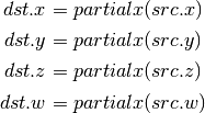
partialx(x) Derivative of x relative to fragment’s X.
partialy(x) Derivative of x relative to fragment’s Y.
pop() Pop from stack.
x to the power y.
push(x) Push x on stack.
round(x) Round x.
trunc(x) Truncate x, i.e. drop the fraction bits.
Keywords
discard Discard fragment.
pc Program counter.
target Label of target instruction.
Other tokens
Declaration
Declares a register that is will be referenced as an operand in Instruction tokens.
File field contains register file that is being declared and is one of TGSI_FILE.
UsageMask field specifies which of the register components can be accessed and is one of TGSI_WRITEMASK.
The Local flag specifies that a given value isn’t intended for subroutine parameter passing and, as a result, the implementation isn’t required to give any guarantees of it being preserved across subroutine boundaries. As it’s merely a compiler hint, the implementation is free to ignore it.
If Dimension flag is set to 1, a Declaration Dimension token follows.
If Semantic flag is set to 1, a Declaration Semantic token follows.
If Interpolate flag is set to 1, a Declaration Interpolate token follows.
If file is TGSI_FILE_RESOURCE, a Declaration Resource token follows.
If Array flag is set to 1, a Declaration Array token follows.
Array Declaration
Declarations can optional have an ArrayID attribute which can be referred by indirect addressing operands. An ArrayID of zero is reserved and treaded as if no ArrayID is specified.
If an indirect addressing operand refers to a specific declaration by using an ArrayID only the registers in this declaration are guaranteed to be accessed, accessing any register outside this declaration results in undefined behavior. Note that for compatibility the effective index is zero-based and not relative to the specified declaration
If no ArrayID is specified with an indirect addressing operand the whole register file might be accessed by this operand. This is strongly discouraged and will prevent packing of scalar/vec2 arrays and effective alias analysis.
Declaration Semantic
Vertex and fragment shader input and output registers may be labeled with semantic information consisting of a name and index.
Follows Declaration token if Semantic bit is set.
Since its purpose is to link a shader with other stages of the pipeline, it is valid to follow only those Declaration tokens that declare a register either in INPUT or OUTPUT file.
SemanticName field contains the semantic name of the register being declared. There is no default value.
SemanticIndex is an optional subscript that can be used to distinguish different register declarations with the same semantic name. The default value is 0.
The meanings of the individual semantic names are explained in the following sections.
TGSI_SEMANTIC_POSITION
For vertex shaders, TGSI_SEMANTIC_POSITION indicates the vertex shader output register which contains the homogeneous vertex position in the clip space coordinate system. After clipping, the X, Y and Z components of the vertex will be divided by the W value to get normalized device coordinates.
For fragment shaders, TGSI_SEMANTIC_POSITION is used to indicate that fragment shader input contains the fragment’s window position. The X component starts at zero and always increases from left to right. The Y component starts at zero and always increases but Y=0 may either indicate the top of the window or the bottom depending on the fragment coordinate origin convention (see TGSI_PROPERTY_FS_COORD_ORIGIN). The Z coordinate ranges from 0 to 1 to represent depth from the front to the back of the Z buffer. The W component contains the interpolated reciprocal of the vertex position W component (corresponding to gl_Fragcoord, but unlike d3d10 which interpolates the same 1/w but then gives back the reciprocal of the interpolated value).
Fragment shaders may also declare an output register with TGSI_SEMANTIC_POSITION. Only the Z component is writable. This allows the fragment shader to change the fragment’s Z position.
TGSI_SEMANTIC_COLOR
For vertex shader outputs or fragment shader inputs/outputs, this label indicates that the resister contains an R,G,B,A color.
Several shader inputs/outputs may contain colors so the semantic index is used to distinguish them. For example, color[0] may be the diffuse color while color[1] may be the specular color.
This label is needed so that the flat/smooth shading can be applied to the right interpolants during rasterization.
TGSI_SEMANTIC_BCOLOR
Back-facing colors are only used for back-facing polygons, and are only valid in vertex shader outputs. After rasterization, all polygons are front-facing and COLOR and BCOLOR end up occupying the same slots in the fragment shader, so all BCOLORs effectively become regular COLORs in the fragment shader.
TGSI_SEMANTIC_FOG
Vertex shader inputs and outputs and fragment shader inputs may be labeled with TGSI_SEMANTIC_FOG to indicate that the register contains a fog coordinate. Typically, the fragment shader will use the fog coordinate to compute a fog blend factor which is used to blend the normal fragment color with a constant fog color. But fog coord really is just an ordinary vec4 register like regular semantics.
TGSI_SEMANTIC_PSIZE
Vertex shader input and output registers may be labeled with TGIS_SEMANTIC_PSIZE to indicate that the register contains a point size in the form (S, 0, 0, 1). The point size controls the width or diameter of points for rasterization. This label cannot be used in fragment shaders.
When using this semantic, be sure to set the appropriate state in the Rasterizer first.
TGSI_SEMANTIC_TEXCOORD
Only available if PIPE_CAP_TGSI_TEXCOORD is exposed !
Vertex shader outputs and fragment shader inputs may be labeled with this semantic to make them replaceable by sprite coordinates via the sprite_coord_enable state in the Rasterizer. The semantic index permitted with this semantic is limited to <= 7.
If the driver does not support TEXCOORD, sprite coordinate replacement applies to inputs with the GENERIC semantic instead.
The intended use case for this semantic is gl_TexCoord.
TGSI_SEMANTIC_PCOORD
Only available if PIPE_CAP_TGSI_TEXCOORD is exposed !
Fragment shader inputs may be labeled with TGSI_SEMANTIC_PCOORD to indicate that the register contains sprite coordinates in the form (x, y, 0, 1), if the current primitive is a point and point sprites are enabled. Otherwise, the contents of the register are undefined.
The intended use case for this semantic is gl_PointCoord.
TGSI_SEMANTIC_GENERIC
All vertex/fragment shader inputs/outputs not labeled with any other semantic label can be considered to be generic attributes. Typical uses of generic inputs/outputs are texcoords and user-defined values.
TGSI_SEMANTIC_NORMAL
Indicates that a vertex shader input is a normal vector. This is typically only used for legacy graphics APIs.
TGSI_SEMANTIC_FACE
This label applies to fragment shader inputs only and indicates that the register contains front/back-face information of the form (F, 0, 0, 1). The first component will be positive when the fragment belongs to a front-facing polygon, and negative when the fragment belongs to a back-facing polygon.
TGSI_SEMANTIC_EDGEFLAG
For vertex shaders, this sematic label indicates that an input or output is a boolean edge flag. The register layout is [F, x, x, x] where F is 0.0 or 1.0 and x = don’t care. Normally, the vertex shader simply copies the edge flag input to the edgeflag output.
Edge flags are used to control which lines or points are actually drawn when the polygon mode converts triangles/quads/polygons into points or lines.
TGSI_SEMANTIC_STENCIL
For fragment shaders, this semantic label indicates that an output is a writable stencil reference value. Only the Y component is writable. This allows the fragment shader to change the fragments stencilref value.
TGSI_SEMANTIC_VIEWPORT_INDEX
For geometry shaders, this semantic label indicates that an output contains the index of the viewport (and scissor) to use. This is an integer value, and only the X component is used.
TGSI_SEMANTIC_LAYER
For geometry shaders, this semantic label indicates that an output contains the layer value to use for the color and depth/stencil surfaces. This is an integer value, and only the X component is used. (Also known as rendertarget array index.)
TGSI_SEMANTIC_CULLDIST
Used as distance to plane for performing application-defined culling of individual primitives against a plane. When components of vertex elements are given this label, these values are assumed to be a float32 signed distance to a plane. Primitives will be completely discarded if the plane distance for all of the vertices in the primitive are < 0. If a vertex has a cull distance of NaN, that vertex counts as “out” (as if its < 0); The limits on both clip and cull distances are bound by the PIPE_MAX_CLIP_OR_CULL_DISTANCE_COUNT define which defines the maximum number of components that can be used to hold the distances and by the PIPE_MAX_CLIP_OR_CULL_DISTANCE_ELEMENT_COUNT which specifies the maximum number of registers which can be annotated with those semantics.
TGSI_SEMANTIC_CLIPDIST
When components of vertex elements are identified this way, these values are each assumed to be a float32 signed distance to a plane. Primitive setup only invokes rasterization on pixels for which the interpolated plane distances are >= 0. Multiple clip planes can be implemented simultaneously, by annotating multiple components of one or more vertex elements with the above specified semantic. The limits on both clip and cull distances are bound by the PIPE_MAX_CLIP_OR_CULL_DISTANCE_COUNT define which defines the maximum number of components that can be used to hold the distances and by the PIPE_MAX_CLIP_OR_CULL_DISTANCE_ELEMENT_COUNT which specifies the maximum number of registers which can be annotated with those semantics.
TGSI_SEMANTIC_SAMPLEID
For fragment shaders, this semantic label indicates that a system value contains the current sample id (i.e. gl_SampleID). This is an integer value, and only the X component is used.
TGSI_SEMANTIC_SAMPLEPOS
For fragment shaders, this semantic label indicates that a system value contains the current sample’s position (i.e. gl_SamplePosition). Only the X and Y values are used.
TGSI_SEMANTIC_SAMPLEMASK
For fragment shaders, this semantic label indicates that an output contains the sample mask used to disable further sample processing (i.e. gl_SampleMask). Only the X value is used, up to 32x MS.
TGSI_SEMANTIC_INVOCATIONID
For geometry shaders, this semantic label indicates that a system value contains the current invocation id (i.e. gl_InvocationID). This is an integer value, and only the X component is used.
TGSI_SEMANTIC_INSTANCEID
For vertex shaders, this semantic label indicates that a system value contains the current instance id (i.e. gl_InstanceID). It does not include the base instance. This is an integer value, and only the X component is used.
TGSI_SEMANTIC_VERTEXID
For vertex shaders, this semantic label indicates that a system value contains the current vertex id (i.e. gl_VertexID). It does (unlike in d3d10) include the base vertex. This is an integer value, and only the X component is used.
TGSI_SEMANTIC_VERTEXID_NOBASE
For vertex shaders, this semantic label indicates that a system value contains the current vertex id without including the base vertex (this corresponds to d3d10 vertex id, so TGSI_SEMANTIC_VERTEXID_NOBASE + TGSI_SEMANTIC_BASEVERTEX == TGSI_SEMANTIC_VERTEXID). This is an integer value, and only the X component is used.
TGSI_SEMANTIC_BASEVERTEX
For vertex shaders, this semantic label indicates that a system value contains the base vertex (i.e. gl_BaseVertex). Note that for non-indexed draw calls, this contains the first (or start) value instead. This is an integer value, and only the X component is used.
TGSI_SEMANTIC_PRIMID
For geometry and fragment shaders, this semantic label indicates the value contains the primitive id (i.e. gl_PrimitiveID). This is an integer value, and only the X component is used. FIXME: This right now can be either a ordinary input or a system value...
Declaration Interpolate
This token is only valid for fragment shader INPUT declarations.
The Interpolate field specifes the way input is being interpolated by the rasteriser and is one of TGSI_INTERPOLATE_*.
The Location field specifies the location inside the pixel that the interpolation should be done at, one of TGSI_INTERPOLATE_LOC_*. Note that when per-sample shading is enabled, the implementation may choose to interpolate at the sample irrespective of the Location field.
The CylindricalWrap bitfield specifies which register components should be subject to cylindrical wrapping when interpolating by the rasteriser. If TGSI_CYLINDRICAL_WRAP_X is set to 1, the X component should be interpolated according to cylindrical wrapping rules.
Declaration Sampler View
Follows Declaration token if file is TGSI_FILE_SAMPLER_VIEW.
DCL SVIEW[#], resource, type(s)
Declares a shader input sampler view and assigns it to a SVIEW[#] register.
resource can be one of BUFFER, 1D, 2D, 3D, 1DArray and 2DArray.
type must be 1 or 4 entries (if specifying on a per-component level) out of UNORM, SNORM, SINT, UINT and FLOAT.
Declaration Resource
Follows Declaration token if file is TGSI_FILE_RESOURCE.
DCL RES[#], resource [, WR] [, RAW]
Declares a shader input resource and assigns it to a RES[#] register.
resource can be one of BUFFER, 1D, 2D, 3D, CUBE, 1DArray and 2DArray.
If the RAW keyword is not specified, the texture data will be subject to conversion, swizzling and scaling as required to yield the specified data type from the physical data format of the bound resource.
If the RAW keyword is specified, no channel conversion will be performed: the values read for each of the channels (X,Y,Z,W) will correspond to consecutive words in the same order and format they’re found in memory. No element-to-address conversion will be performed either: the value of the provided X coordinate will be interpreted in byte units instead of texel units. The result of accessing a misaligned address is undefined.
Usage of the STORE opcode is only allowed if the WR (writable) flag is set.
Properties
Properties are general directives that apply to the whole TGSI program.
FS_COORD_ORIGIN
Specifies the fragment shader TGSI_SEMANTIC_POSITION coordinate origin. The default value is UPPER_LEFT.
If UPPER_LEFT, the position will be (0,0) at the upper left corner and increase downward and rightward. If LOWER_LEFT, the position will be (0,0) at the lower left corner and increase upward and rightward.
OpenGL defaults to LOWER_LEFT, and is configurable with the GL_ARB_fragment_coord_conventions extension.
DirectX 9/10 use UPPER_LEFT.
FS_COORD_PIXEL_CENTER
Specifies the fragment shader TGSI_SEMANTIC_POSITION pixel center convention. The default value is HALF_INTEGER.
If HALF_INTEGER, the fractionary part of the position will be 0.5 If INTEGER, the fractionary part of the position will be 0.0
Note that this does not affect the set of fragments generated by rasterization, which is instead controlled by half_pixel_center in the rasterizer.
OpenGL defaults to HALF_INTEGER, and is configurable with the GL_ARB_fragment_coord_conventions extension.
DirectX 9 uses INTEGER. DirectX 10 uses HALF_INTEGER.
FS_COLOR0_WRITES_ALL_CBUFS
Specifies that writes to the fragment shader color 0 are replicated to all bound cbufs. This facilitates OpenGL’s fragColor output vs fragData[0] where fragData is directed to a single color buffer, but fragColor is broadcast.
VS_PROHIBIT_UCPS
If this property is set on the program bound to the shader stage before the fragment shader, user clip planes should have no effect (be disabled) even if that shader does not write to any clip distance outputs and the rasterizer’s clip_plane_enable is non-zero. This property is only supported by drivers that also support shader clip distance outputs. This is useful for APIs that don’t have UCPs and where clip distances written by a shader cannot be disabled.
GS_INVOCATIONS
Specifies the number of times a geometry shader should be executed for each input primitive. Each invocation will have a different TGSI_SEMANTIC_INVOCATIONID system value set. If not specified, assumed to be 1.
VS_WINDOW_SPACE_POSITION
If this property is set on the vertex shader, the TGSI_SEMANTIC_POSITION output is assumed to contain window space coordinates. Division of X,Y,Z by W and the viewport transformation are disabled, and 1/W is directly taken from the 4-th component of the shader output. Naturally, clipping is not performed on window coordinates either. The effect of this property is undefined if a geometry or tessellation shader are in use.
Texture Sampling and Texture Formats
This table shows how texture image components are returned as (x,y,z,w) tuples by TGSI texture instructions, such as TEX, TXD, and TXP. For reference, OpenGL and Direct3D conventions are shown as well.
| Texture Components | Gallium | OpenGL | Direct3D 9 |
|---|---|---|---|
| R | (r, 0, 0, 1) | (r, 0, 0, 1) | (r, 1, 1, 1) |
| RG | (r, g, 0, 1) | (r, g, 0, 1) | (r, g, 1, 1) |
| RGB | (r, g, b, 1) | (r, g, b, 1) | (r, g, b, 1) |
| RGBA | (r, g, b, a) | (r, g, b, a) | (r, g, b, a) |
| A | (0, 0, 0, a) | (0, 0, 0, a) | (0, 0, 0, a) |
| L | (l, l, l, 1) | (l, l, l, 1) | (l, l, l, 1) |
| LA | (l, l, l, a) | (l, l, l, a) | (l, l, l, a) |
| I | (i, i, i, i) | (i, i, i, i) | N/A |
| UV | XXX TBD | (0, 0, 0, 1) [1] | (u, v, 1, 1) |
| Z | XXX TBD | (z, z, z, 1) [2] | (0, z, 0, 1) |
| S | (s, s, s, s) | unknown | unknown |
| [1] | http://www.opengl.org/registry/specs/ATI/envmap_bumpmap.txt |
| [2] | the default is (z, z, z, 1) but may also be (0, 0, 0, z) or (z, z, z, z) depending on the value of GL_DEPTH_TEXTURE_MODE. |