Welcome to Gallium’s documentation!
Contents:
Introduction
What is Gallium?
Gallium is essentially an API for writing graphics drivers in a largely device-agnostic fashion. It provides several objects which encapsulate the core services of graphics hardware in a straightforward manner.
Debugging
Debugging utilities in gallium.
Debug Variables
All drivers respond to a set of common debug environment variables, as well as some driver-specific variables. Set them as normal environment variables for the platform or operating system you are running. For example, for Linux this can be done by typing “export var=value” into a console and then running the program from that console.
Common
- GALLIUM_PRINT_OPTIONS Type: bool Default: false
This option controls if the debug variables should be printed to stderr. This is probably the most useful variable, since it allows you to find which variables a driver uses.
- GALLIUM_RBUG Type: bool Default: false
Controls if the Remote Debugger should be used.
- GALLIUM_TRACE Type: string Default: ""
If set, this variable will cause the Trace output to be written to the specified file. Paths may be relative or absolute; relative paths are relative to the working directory. For example, setting it to “trace.xml” will cause the trace to be written to a file of the same name in the working directory.
- GALLIUM_DUMP_CPU Type: bool Default: false
Dump information about the current CPU that the driver is running on.
- TGSI_PRINT_SANITY Type: bool Default: false
Gallium has a built-in shader sanity checker. This option controls whether the shader sanity checker prints its warnings and errors to stderr.
- DRAW_USE_LLVM Type: bool Default: false
Whether the Draw module will attempt to use LLVM for vertex and geometry shaders.
Driver-specific
- I915_DEBUG Type: flags Default: 0x0
Debug Flags for the i915 driver.
- I915_NO_HW Type: bool Default: false
Stop the i915 driver from submitting commands to the hardware.
- I915_DUMP_CMD Type: bool Default: false
Dump all commands going to the hardware.
- LP_DEBUG Type: flags Default: 0x0
Debug Flags for the llvmpipe driver.
- LP_NUM_THREADS Type: int Default: number of CPUs
Number of threads that the llvmpipe driver should use.
- FD_MESA_DEBUG Type: flags Default: 0x0
Debug Flags for the freedreno driver.
Flags
The variables of type “flags” all take a string with comma-separated flags to enable different debugging for different parts of the drivers or state tracker. If set to “help”, the driver will print a list of flags which the variable accepts. Order does not matter.
Remote Debugger
The remote debugger, commonly known as rbug, allows for runtime inspections of Context, Screen, Resources and derived objects and Shader objects; and pausing and stepping of Draw calls. Is used with rbug-gui which is hosted outside of the main mesa repository. rbug is can be used over a network connection, so the debugger does not need to be on the same machine.
TGSI
TGSI, Tungsten Graphics Shader Infrastructure, is an intermediate language for describing shaders. Since Gallium is inherently shaderful, shaders are an important part of the API. TGSI is the only intermediate representation used by all drivers.
Basics
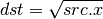
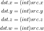
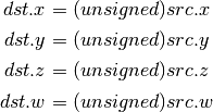
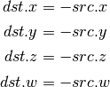
All TGSI instructions, known as opcodes, operate on arbitrary-precision floating-point four-component vectors. An opcode may have up to one destination register, known as dst, and between zero and three source registers, called src0 through src2, or simply src if there is only one.
Some instructions, like I2F, permit re-interpretation of vector components as integers. Other instructions permit using registers as two-component vectors with double precision; see Double ISA.
When an instruction has a scalar result, the result is usually copied into each of the components of dst. When this happens, the result is said to be replicated to dst. RCP is one such instruction.
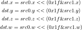
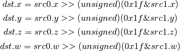
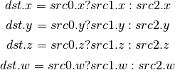
Modifiers
TGSI supports modifiers on inputs (as well as saturate modifier on instructions).
For inputs which have a floating point type, both absolute value and negation modifiers are supported (with absolute value being applied first). TGSI_OPCODE_MOV is considered to have float input type for applying modifiers.
For inputs which have signed or unsigned type only the negate modifier is supported.
Instruction Set
Core ISA
These opcodes are guaranteed to be available regardless of the driver being used.
- ARL (Address Register Load)
- MOV (Move)
- LIT (Light Coefficients)
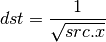
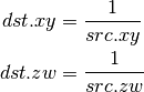
- RCP (Reciprocal)
This instruction replicates its result.

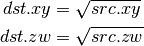
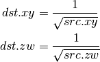
- RSQ (Reciprocal Square Root)
This instruction replicates its result. The results are undefined for src <= 0.
- SQRT (Square Root)
This instruction replicates its result. The results are undefined for src < 0.
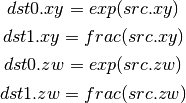
- EXP (Approximate Exponential Base 2)
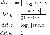
- LOG (Approximate Logarithm Base 2)
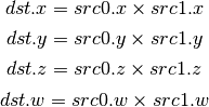
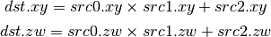
- MUL (Multiply)
- ADD (Add)
- DP3 (3-component Dot Product)
This instruction replicates its result.

- DP4 (4-component Dot Product)
This instruction replicates its result.

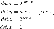
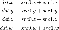
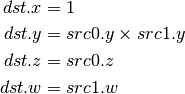
- DST (Distance Vector)
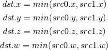
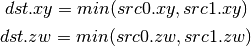
- MIN (Minimum)
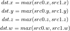
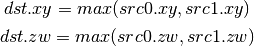
- MAX (Maximum)
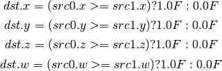
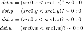
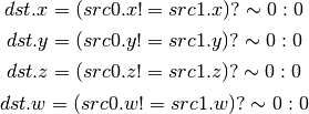
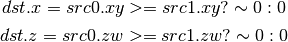
- SLT (Set On Less Than)
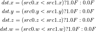
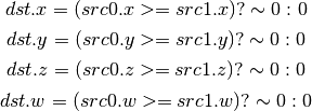
- SGE (Set On Greater Equal Than)
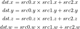
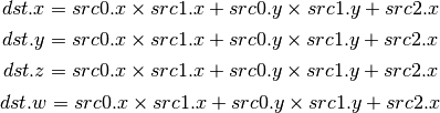
- MAD (Multiply And Add)
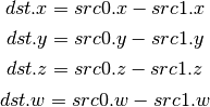
- SUB (Subtract)
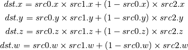
- LRP (Linear Interpolate)
- FMA (Fused Multiply-Add)
Perform a * b + c with no intermediate rounding step.
- DP2A (2-component Dot Product And Add)
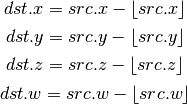
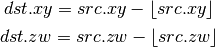
- FRC (Fraction)
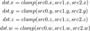
- CLAMP (Clamp)
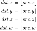
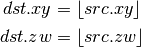
- FLR (Floor)
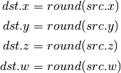
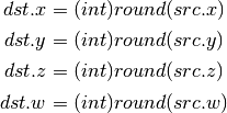
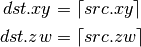
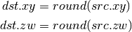
- ROUND (Round)
- EX2 (Exponential Base 2)
This instruction replicates its result.

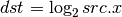
- LG2 (Logarithm Base 2)
This instruction replicates its result.
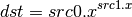
- POW (Power)
This instruction replicates its result.
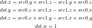
- XPD (Cross Product)
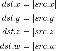
- ABS (Absolute)
- DPH (Homogeneous Dot Product)
This instruction replicates its result.

- COS (Cosine)
This instruction replicates its result.

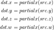
- DDX, DDX_FINE (Derivative Relative To X)
The fine variant is only used when PIPE_CAP_TGSI_FS_FINE_DERIVATIVE is advertised. When it is, the fine version guarantees one derivative per row while DDX is allowed to be the same for the entire 2x2 quad.
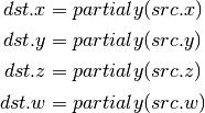
- DDY, DDY_FINE (Derivative Relative To Y)
The fine variant is only used when PIPE_CAP_TGSI_FS_FINE_DERIVATIVE is advertised. When it is, the fine version guarantees one derivative per column while DDY is allowed to be the same for the entire 2x2 quad.
- PK2H (Pack Two 16-bit Floats)
TBD
- PK2US (Pack Two Unsigned 16-bit Scalars)
TBD
- PK4B (Pack Four Signed 8-bit Scalars)
TBD
- PK4UB (Pack Four Unsigned 8-bit Scalars)
TBD
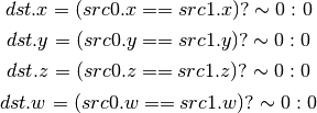
- SEQ (Set On Equal)
- SGT (Set On Greater Than)

- SIN (Sine)
This instruction replicates its result.

- SLE (Set On Less Equal Than)

- SNE (Set On Not Equal)
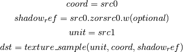
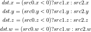
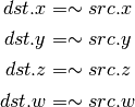
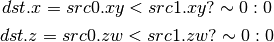
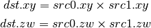
- TEX (Texture Lookup)
for array textures src0.y contains the slice for 1D, and src0.z contain the slice for 2D.
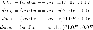
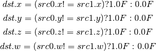
for shadow textures with no arrays (and not cube map), src0.z contains the reference value.
for shadow textures with arrays, src0.z contains the reference value for 1D arrays, and src0.w contains the reference value for 2D arrays and cube maps.
for cube map array shadow textures, the reference value cannot be passed in src0.w, and TEX2 must be used instead.
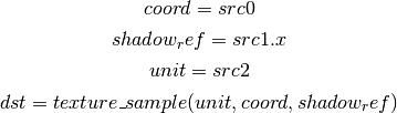
- TEX2 (Texture Lookup (for shadow cube map arrays only))
this is the same as TEX, but uses another reg to encode the reference value.
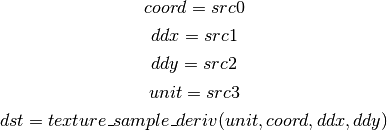
- TXD (Texture Lookup with Derivatives)
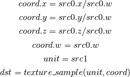
- TXP (Projective Texture Lookup)
- UP2H (Unpack Two 16-Bit Floats)
TBD
Note
Considered for removal.
- UP2US (Unpack Two Unsigned 16-Bit Scalars)
TBD
Note
Considered for removal.
- UP4B (Unpack Four Signed 8-Bit Values)
TBD
Note
Considered for removal.
- UP4UB (Unpack Four Unsigned 8-Bit Scalars)
TBD
Note
Considered for removal.
- ARR (Address Register Load With Round)
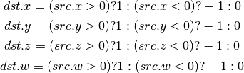
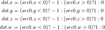
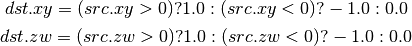
- SSG (Set Sign)
- CMP (Compare)
- KILL_IF (Conditional Discard)
Conditional discard. Allowed in fragment shaders only.

- KILL (Discard)
Unconditional discard. Allowed in fragment shaders only.
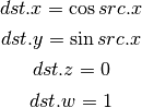
- SCS (Sine Cosine)
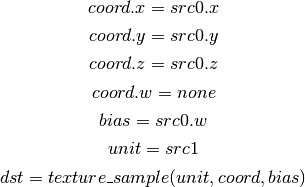
- TXB (Texture Lookup With Bias)
for cube map array textures and shadow cube maps, the bias value cannot be passed in src0.w, and TXB2 must be used instead.
if the target is a shadow texture, the reference value is always in src.z (this prevents shadow 3d and shadow 2d arrays from using this instruction, but this is not needed).
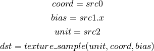
- TXB2 (Texture Lookup With Bias (some cube maps only))
this is the same as TXB, but uses another reg to encode the lod bias value for cube map arrays and shadow cube maps. Presumably shadow 2d arrays and shadow 3d targets could use this encoding too, but this is not legal.
shadow cube map arrays are neither possible nor required.
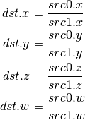
- DIV (Divide)
- DP2 (2-component Dot Product)
This instruction replicates its result.

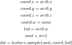
- TXL (Texture Lookup With explicit LOD)
for cube map array textures, the explicit lod value cannot be passed in src0.w, and TXL2 must be used instead.
if the target is a shadow texture, the reference value is always in src.z (this prevents shadow 3d / 2d array / cube targets from using this instruction, but this is not needed).
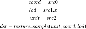
- TXL2 (Texture Lookup With explicit LOD (for cube map arrays only))
this is the same as TXL, but uses another reg to encode the explicit lod value. Presumably shadow 3d / 2d array / cube targets could use this encoding too, but this is not legal.
shadow cube map arrays are neither possible nor required.
- PUSHA (Push Address Register On Stack)
push(src.x) push(src.y) push(src.z) push(src.w)
Note
Considered for cleanup.
Note
Considered for removal.
- POPA (Pop Address Register From Stack)
dst.w = pop() dst.z = pop() dst.y = pop() dst.x = pop()
Note
Considered for cleanup.
Note
Considered for removal.
- CALLNZ (Subroutine Call If Not Zero)
TBD
Note
Considered for cleanup.
Note
Considered for removal.
Compute ISA
These opcodes are primarily provided for special-use computational shaders. Support for these opcodes indicated by a special pipe capability bit (TBD).
XXX doesn’t look like most of the opcodes really belong here.
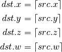
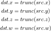
- CEIL (Ceiling)
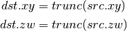
- TRUNC (Truncate)
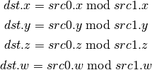
- MOD (Modulus)
- UARL (Integer Address Register Load)
Moves the contents of the source register, assumed to be an integer, into the destination register, which is assumed to be an address (ADDR) register.
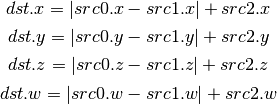
- SAD (Sum Of Absolute Differences)
- TXF (Texel Fetch)
As per NV_gpu_shader4, extract a single texel from a specified texture image. The source sampler may not be a CUBE or SHADOW. src 0 is a four-component signed integer vector used to identify the single texel accessed. 3 components + level. Just like texture instructions, an optional offset vector is provided, which is subject to various driver restrictions (regarding range, source of offsets). TXF(uint_vec coord, int_vec offset).
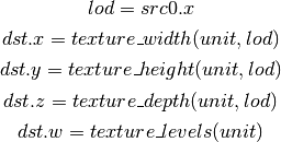
- TXQ (Texture Size Query)
As per NV_gpu_program4, retrieve the dimensions of the texture depending on the target. For 1D (width), 2D/RECT/CUBE (width, height), 3D (width, height, depth), 1D array (width, layers), 2D array (width, height, layers). Also return the number of accessible levels (last_level - first_level + 1) in W.
For components which don’t return a resource dimension, their value is undefined.
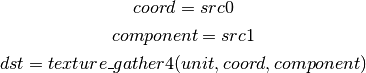
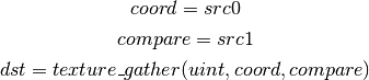
- TG4 (Texture Gather)
As per ARB_texture_gather, gathers the four texels to be used in a bi-linear filtering operation and packs them into a single register. Only works with 2D, 2D array, cubemaps, and cubemaps arrays. For 2D textures, only the addressing modes of the sampler and the top level of any mip pyramid are used. Set W to zero. It behaves like the TEX instruction, but a filtered sample is not generated. The four samples that contribute to filtering are placed into xyzw in clockwise order, starting with the (u,v) texture coordinate delta at the following locations (-, +), (+, +), (+, -), (-, -), where the magnitude of the deltas are half a texel.
PIPE_CAP_TEXTURE_SM5 enhances this instruction to support shadow per-sample depth compares, single component selection, and a non-constant offset. It doesn’t allow support for the GL independent offset to get i0,j0. This would require another CAP is hw can do it natively. For now we lower that before TGSI.
(with SM5 - cube array shadow)
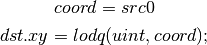
- LODQ (level of detail query)
Compute the LOD information that the texture pipe would use to access the texture. The Y component contains the computed LOD lambda_prime. The X component contains the LOD that will be accessed, based on min/max lod’s and mipmap filters.
Integer ISA
These opcodes are used for integer operations. Support for these opcodes indicated by PIPE_SHADER_CAP_INTEGERS (all of them?)
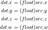
- I2F (Signed Integer To Float)
Rounding is unspecified (round to nearest even suggested).
- U2F (Unsigned Integer To Float)
Rounding is unspecified (round to nearest even suggested).
- F2I (Float to Signed Integer)
Rounding is towards zero (truncate). Values outside signed range (including NaNs) produce undefined results.
- F2U (Float to Unsigned Integer)
Rounding is towards zero (truncate). Values outside unsigned range (including NaNs) produce undefined results.
- UADD (Integer Add)
This instruction works the same for signed and unsigned integers. The low 32bit of the result is returned.
- UMAD (Integer Multiply And Add)
This instruction works the same for signed and unsigned integers. The multiplication returns the low 32bit (as does the result itself).
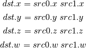
- UMUL (Integer Multiply)
This instruction works the same for signed and unsigned integers. The low 32bit of the result is returned.
- IMUL_HI (Signed Integer Multiply High Bits)
The high 32bits of the multiplication of 2 signed integers are returned.
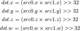
- UMUL_HI (Unsigned Integer Multiply High Bits)
The high 32bits of the multiplication of 2 unsigned integers are returned.
- IDIV (Signed Integer Division)
TBD: behavior for division by zero.
- UDIV (Unsigned Integer Division)
For division by zero, 0xffffffff is returned.
- UMOD (Unsigned Integer Remainder)
If second arg is zero, 0xffffffff is returned.
- NOT (Bitwise Not)
- AND (Bitwise And)
- OR (Bitwise Or)
- XOR (Bitwise Xor)
- IMAX (Maximum of Signed Integers)
- UMAX (Maximum of Unsigned Integers)
- IMIN (Minimum of Signed Integers)
- UMIN (Minimum of Unsigned Integers)
- SHL (Shift Left)
The shift count is masked with 0x1f before the shift is applied.
- ISHR (Arithmetic Shift Right (of Signed Integer))
The shift count is masked with 0x1f before the shift is applied.

- USHR (Logical Shift Right)
The shift count is masked with 0x1f before the shift is applied.
- UCMP (Integer Conditional Move)
- ISSG (Integer Set Sign)
- FSLT (Float Set On Less Than (ordered))
Same comparison as SLT but returns integer instead of 1.0/0.0 float
- ISLT (Signed Integer Set On Less Than)
- USLT (Unsigned Integer Set On Less Than)
- FSGE (Float Set On Greater Equal Than (ordered))
Same comparison as SGE but returns integer instead of 1.0/0.0 float
- ISGE (Signed Integer Set On Greater Equal Than)
- USGE (Unsigned Integer Set On Greater Equal Than)
- FSEQ (Float Set On Equal (ordered))
Same comparison as SEQ but returns integer instead of 1.0/0.0 float
- USEQ (Integer Set On Equal)
- FSNE (Float Set On Not Equal (unordered))
Same comparison as SNE but returns integer instead of 1.0/0.0 float
- USNE (Integer Set On Not Equal)
- INEG (Integer Negate)
Two’s complement.
- IABS (Integer Absolute Value)
Bitwise ISA
These opcodes are used for bit-level manipulation of integers.
- IBFE (Signed Bitfield Extract)
See SM5 instruction of the same name. Extracts a set of bits from the input, and sign-extends them if the high bit of the extracted window is set.
Pseudocode:
def ibfe(value, offset, bits):
  offset = offset & 0x1f
  bits = bits & 0x1f
  if bits == 0: return 0
  # Note: >> sign-extends
  if width + offset < 32:
    return (value << (32 - offset - bits)) >> (32 - bits)
  else:
    return value >> offset
- UBFE (Unsigned Bitfield Extract)
See SM5 instruction of the same name. Extracts a set of bits from the input, without any sign-extension.
Pseudocode:
def ubfe(value, offset, bits):
  offset = offset & 0x1f
  bits = bits & 0x1f
  if bits == 0: return 0
  # Note: >> does not sign-extend
  if width + offset < 32:
    return (value << (32 - offset - bits)) >> (32 - bits)
  else:
    return value >> offset
- BFI (Bitfield Insert)
See SM5 instruction of the same name. Replaces a bit region of ‘base’ with the low bits of ‘insert’.
Pseudocode:
def bfi(base, insert, offset, bits):
  offset = offset & 0x1f
  bits = bits & 0x1f
  mask = ((1 << bits) - 1) << offset
  return ((insert << offset) & mask) | (base & ~mask)
- BREV (Bitfield Reverse)
See SM5 instruction BFREV. Reverses the bits of the argument.
- POPC (Population Count)
See SM5 instruction COUNTBITS. Counts the number of set bits in the argument.
- LSB (Index of lowest set bit)
See SM5 instruction FIRSTBIT_LO. Computes the 0-based index of the first set bit of the argument. Returns -1 if none are set.
- IMSB (Index of highest non-sign bit)
See SM5 instruction FIRSTBIT_SHI. Computes the 0-based index of the highest non-sign bit of the argument (i.e. highest 0 bit for negative numbers, highest 1 bit for positive numbers). Returns -1 if all bits are the same (i.e. for inputs 0 and -1).
- UMSB (Index of highest set bit)
See SM5 instruction FIRSTBIT_HI. Computes the 0-based index of the highest set bit of the argument. Returns -1 if none are set.
Geometry ISA
These opcodes are only supported in geometry shaders; they have no meaning in any other type of shader.
- EMIT (Emit)
Generate a new vertex for the current primitive into the specified vertex stream using the values in the output registers.
- ENDPRIM (End Primitive)
Complete the current primitive in the specified vertex stream (consisting of the emitted vertices), and start a new one.
GLSL ISA
These opcodes are part of GLSL‘s opcode set. Support for these opcodes is determined by a special capability bit, GLSL. Some require glsl version 1.30 (UIF/BREAKC/SWITCH/CASE/DEFAULT/ENDSWITCH).
- CAL (Subroutine Call)
push(pc) pc = target
- RET (Subroutine Call Return)
pc = pop()
- CONT (Continue)
Unconditionally moves the point of execution to the instruction after the last bgnloop. The instruction must appear within a bgnloop/endloop.
Note
Support for CONT is determined by a special capability bit, TGSI_CONT_SUPPORTED. See Screen for more information.
- BGNLOOP (Begin a Loop)
Start a loop. Must have a matching endloop.
- BGNSUB (Begin Subroutine)
Starts definition of a subroutine. Must have a matching endsub.
- ENDLOOP (End a Loop)
End a loop started with bgnloop.
- ENDSUB (End Subroutine)
Ends definition of a subroutine.
- NOP (No Operation)
Do nothing.
- BRK (Break)
Unconditionally moves the point of execution to the instruction after the next endloop or endswitch. The instruction must appear within a loop/endloop or switch/endswitch.
- BREAKC (Break Conditional)
Conditionally moves the point of execution to the instruction after the next endloop or endswitch. The instruction must appear within a loop/endloop or switch/endswitch. Condition evaluates to true if src0.x != 0 where src0.x is interpreted as an integer register.
Note
Considered for removal as it’s quite inconsistent wrt other opcodes (could emulate with UIF/BRK/ENDIF).
- IF (Float If)
Start an IF ... ELSE .. ENDIF block. Condition evaluates to true if
src0.x != 0.0where src0.x is interpreted as a floating point register.
- UIF (Bitwise If)
Start an UIF ... ELSE .. ENDIF block. Condition evaluates to true if
src0.x != 0where src0.x is interpreted as an integer register.
- ELSE (Else)
Starts an else block, after an IF or UIF statement.
- ENDIF (End If)
Ends an IF or UIF block.
- SWITCH (Switch)
Starts a C-style switch expression. The switch consists of one or multiple CASE statements, and at most one DEFAULT statement. Execution of a statement ends when a BRK is hit, but just like in C falling through to other cases without a break is allowed. Similarly, DEFAULT label is allowed anywhere not just as last statement, and fallthrough is allowed into/from it. CASE src arguments are evaluated at bit level against the SWITCH src argument.
Example:
SWITCH src[0].x
CASE src[0].x
(some instructions here)
(optional BRK here)
DEFAULT
(some instructions here)
(optional BRK here)
CASE src[0].x
(some instructions here)
(optional BRK here)
ENDSWITCH
- CASE (Switch case)
This represents a switch case label. The src arg must be an integer immediate.
- DEFAULT (Switch default)
This represents the default case in the switch, which is taken if no other case matches.
- ENDSWITCH (End of switch)
Ends a switch expression.
Interpolation ISA
The interpolation instructions allow an input to be interpolated in a different way than its declaration. This corresponds to the GLSL 4.00 interpolateAt* functions. The first argument of each of these must come from TGSI_FILE_INPUT.
- INTERP_CENTROID (Interpolate at the centroid)
Interpolates the varying specified by src0 at the centroid
- INTERP_SAMPLE (Interpolate at the specified sample)
Interpolates the varying specified by src0 at the sample id specified by src1.x (interpreted as an integer)
- INTERP_OFFSET (Interpolate at the specified offset)
Interpolates the varying specified by src0 at the offset src1.xy from the pixel center (interpreted as floats)
Double ISA
The double-precision opcodes reinterpret four-component vectors into two-component vectors with doubled precision in each component.
- DADD (Add)
- DSEQ (Set on Equal)
- DSNE (Set on Equal)
- DSLT (Set on Less than)
- DSGE (Set on Greater equal)
- DFRAC (Fraction)
- DTRUNC (Truncate)
- DCEIL (Ceiling)
- DFLR (Floor)
- DROUND (Fraction)
- DSSG (Set Sign)
- DFRACEXP (Convert Number to Fractional and Integral Components)
Like the frexp() routine in many math libraries, this opcode stores the
exponent of its source to dst0, and the significand to dst1, such that
 .
.
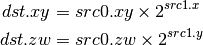
- DLDEXP (Multiply Number by Integral Power of 2)
This opcode is the inverse of DFRACEXP. The second source is an integer.
- DMIN (Minimum)
- DMAX (Maximum)
- DMUL (Multiply)
- DMAD (Multiply And Add)
- DFMA (Fused Multiply-Add)
Perform a * b + c with no intermediate rounding step.
- DRCP (Reciprocal)
- DSQRT (Square Root)
- DRSQ (Reciprocal Square Root)
- F2D (Float to Double)
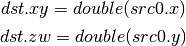
- D2F (Double to Float)
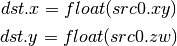
- I2D (Int to Double)
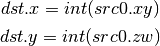
- D2I (Double to Int)
- U2D (Unsigned Int to Double)
- D2U (Double to Unsigned Int)
Resource Sampling Opcodes
Those opcodes follow very closely semantics of the respective Direct3D instructions. If in doubt double check Direct3D documentation. Note that the swizzle on SVIEW (src1) determines texel swizzling after lookup.
- SAMPLE
Using provided address, sample data from the specified texture using the filtering mode identified by the gven sampler. The source data may come from any resource type other than buffers.
Syntax: SAMPLE dst, address, sampler_view, sampler
Example: SAMPLE TEMP[0], TEMP[1], SVIEW[0], SAMP[0]
- SAMPLE_I
Simplified alternative to the SAMPLE instruction. Using the provided integer address, SAMPLE_I fetches data from the specified sampler view without any filtering. The source data may come from any resource type other than CUBE.
Syntax: SAMPLE_I dst, address, sampler_view
Example: SAMPLE_I TEMP[0], TEMP[1], SVIEW[0]
The ‘address’ is specified as unsigned integers. If the ‘address’ is out of range [0...(# texels - 1)] the result of the fetch is always 0 in all components. As such the instruction doesn’t honor address wrap modes, in cases where that behavior is desirable ‘SAMPLE’ instruction should be used. address.w always provides an unsigned integer mipmap level. If the value is out of the range then the instruction always returns 0 in all components. address.yz are ignored for buffers and 1d textures. address.z is ignored for 1d texture arrays and 2d textures.
For 1D texture arrays address.y provides the array index (also as unsigned integer). If the value is out of the range of available array indices [0... (array size - 1)] then the opcode always returns 0 in all components. For 2D texture arrays address.z provides the array index, otherwise it exhibits the same behavior as in the case for 1D texture arrays. The exact semantics of the source address are presented in the table below:
resource type X Y Z W PIPE_BUFFER x ignored PIPE_TEXTURE_1D x mpl PIPE_TEXTURE_2D x y mpl PIPE_TEXTURE_3D x y z mpl PIPE_TEXTURE_RECT x y mpl PIPE_TEXTURE_CUBE not allowed as source PIPE_TEXTURE_1D_ARRAY x idx mpl PIPE_TEXTURE_2D_ARRAY x y idx mpl Where ‘mpl’ is a mipmap level and ‘idx’ is the array index.
- SAMPLE_I_MS
Just like SAMPLE_I but allows fetch data from multi-sampled surfaces.
Syntax: SAMPLE_I_MS dst, address, sampler_view, sample
- SAMPLE_B
Just like the SAMPLE instruction with the exception that an additional bias is applied to the level of detail computed as part of the instruction execution.
Syntax: SAMPLE_B dst, address, sampler_view, sampler, lod_bias
Example: SAMPLE_B TEMP[0], TEMP[1], SVIEW[0], SAMP[0], TEMP[2].x
- SAMPLE_C
Similar to the SAMPLE instruction but it performs a comparison filter. The operands to SAMPLE_C are identical to SAMPLE, except that there is an additional float32 operand, reference value, which must be a register with single-component, or a scalar literal. SAMPLE_C makes the hardware use the current samplers compare_func (in pipe_sampler_state) to compare reference value against the red component value for the surce resource at each texel that the currently configured texture filter covers based on the provided coordinates.
Syntax: SAMPLE_C dst, address, sampler_view.r, sampler, ref_value
Example: SAMPLE_C TEMP[0], TEMP[1], SVIEW[0].r, SAMP[0], TEMP[2].x
- SAMPLE_C_LZ
Same as SAMPLE_C, but LOD is 0 and derivatives are ignored. The LZ stands for level-zero.
Syntax: SAMPLE_C_LZ dst, address, sampler_view.r, sampler, ref_value
Example: SAMPLE_C_LZ TEMP[0], TEMP[1], SVIEW[0].r, SAMP[0], TEMP[2].x
- SAMPLE_D
SAMPLE_D is identical to the SAMPLE opcode except that the derivatives for the source address in the x direction and the y direction are provided by extra parameters.
Syntax: SAMPLE_D dst, address, sampler_view, sampler, der_x, der_y
Example: SAMPLE_D TEMP[0], TEMP[1], SVIEW[0], SAMP[0], TEMP[2], TEMP[3]
- SAMPLE_L
SAMPLE_L is identical to the SAMPLE opcode except that the LOD is provided directly as a scalar value, representing no anisotropy.
Syntax: SAMPLE_L dst, address, sampler_view, sampler, explicit_lod
Example: SAMPLE_L TEMP[0], TEMP[1], SVIEW[0], SAMP[0], TEMP[2].x
- GATHER4
Gathers the four texels to be used in a bi-linear filtering operation and packs them into a single register. Only works with 2D, 2D array, cubemaps, and cubemaps arrays. For 2D textures, only the addressing modes of the sampler and the top level of any mip pyramid are used. Set W to zero. It behaves like the SAMPLE instruction, but a filtered sample is not generated. The four samples that contribute to filtering are placed into xyzw in counter-clockwise order, starting with the (u,v) texture coordinate delta at the following locations (-, +), (+, +), (+, -), (-, -), where the magnitude of the deltas are half a texel.
- SVIEWINFO
Query the dimensions of a given sampler view. dst receives width, height, depth or array size and number of mipmap levels as int4. The dst can have a writemask which will specify what info is the caller interested in.
Syntax: SVIEWINFO dst, src_mip_level, sampler_view
Example: SVIEWINFO TEMP[0], TEMP[1].x, SVIEW[0]
src_mip_level is an unsigned integer scalar. If it’s out of range then returns 0 for width, height and depth/array size but the total number of mipmap is still returned correctly for the given sampler view. The returned width, height and depth values are for the mipmap level selected by the src_mip_level and are in the number of texels. For 1d texture array width is in dst.x, array size is in dst.y and dst.z is 0. The number of mipmaps is still in dst.w. In contrast to d3d10 resinfo, there’s no way in the tgsi instruction encoding to specify the return type (float/rcpfloat/uint), hence always using uint. Also, unlike the SAMPLE instructions, the swizzle on src1 resinfo allowing swizzling dst values is ignored (due to the interaction with rcpfloat modifier which requires some swizzle handling in the state tracker anyway).
- SAMPLE_POS
Query the position of a given sample. dst receives float4 (x, y, 0, 0) indicated where the sample is located. If the resource is not a multi-sample resource and not a render target, the result is 0.
- SAMPLE_INFO
dst receives number of samples in x. If the resource is not a multi-sample resource and not a render target, the result is 0.
Resource Access Opcodes
- LOAD (Fetch data from a shader resource)
Syntax: LOAD dst, resource, address
Example: LOAD TEMP[0], RES[0], TEMP[1]
Using the provided integer address, LOAD fetches data from the specified buffer or texture without any filtering.
The ‘address’ is specified as a vector of unsigned integers. If the ‘address’ is out of range the result is unspecified.
Only the first mipmap level of a resource can be read from using this instruction.
For 1D or 2D texture arrays, the array index is provided as an unsigned integer in address.y or address.z, respectively. address.yz are ignored for buffers and 1D textures. address.z is ignored for 1D texture arrays and 2D textures. address.w is always ignored.
- STORE (Write data to a shader resource)
Syntax: STORE resource, address, src
Example: STORE RES[0], TEMP[0], TEMP[1]
Using the provided integer address, STORE writes data to the specified buffer or texture.
The ‘address’ is specified as a vector of unsigned integers. If the ‘address’ is out of range the result is unspecified.
Only the first mipmap level of a resource can be written to using this instruction.
For 1D or 2D texture arrays, the array index is provided as an unsigned integer in address.y or address.z, respectively. address.yz are ignored for buffers and 1D textures. address.z is ignored for 1D texture arrays and 2D textures. address.w is always ignored.
Inter-thread synchronization opcodes
These opcodes are intended for communication between threads running within the same compute grid. For now they’re only valid in compute programs.
- MFENCE (Memory fence)
Syntax: MFENCE resource
Example: MFENCE RES[0]
This opcode forces strong ordering between any memory access operations that affect the specified resource. This means that previous loads and stores (and only those) will be performed and visible to other threads before the program execution continues.
- LFENCE (Load memory fence)
Syntax: LFENCE resource
Example: LFENCE RES[0]
Similar to MFENCE, but it only affects the ordering of memory loads.
- SFENCE (Store memory fence)
Syntax: SFENCE resource
Example: SFENCE RES[0]
Similar to MFENCE, but it only affects the ordering of memory stores.
- BARRIER (Thread group barrier)
BARRIER
This opcode suspends the execution of the current thread until all the remaining threads in the working group reach the same point of the program. Results are unspecified if any of the remaining threads terminates or never reaches an executed BARRIER instruction.
Atomic opcodes
These opcodes provide atomic variants of some common arithmetic and logical operations. In this context atomicity means that another concurrent memory access operation that affects the same memory location is guaranteed to be performed strictly before or after the entire execution of the atomic operation.
For the moment they’re only valid in compute programs.
- ATOMUADD (Atomic integer addition)
Syntax: ATOMUADD dst, resource, offset, src
Example: ATOMUADD TEMP[0], RES[0], TEMP[1], TEMP[2]
The following operation is performed atomically on each component:
![dst_i = resource[offset]_i
resource[offset]_i = dst_i + src_i](_images/math/8f9a9ca582903138a5ed9909dd56eb8a692f8c51.png)
- ATOMXCHG (Atomic exchange)
Syntax: ATOMXCHG dst, resource, offset, src
Example: ATOMXCHG TEMP[0], RES[0], TEMP[1], TEMP[2]
The following operation is performed atomically on each component:
![dst_i = resource[offset]_i
resource[offset]_i = src_i](_images/math/2a35d6e3026b6bd5c880a2a6f48529e1535d2ff3.png)
- ATOMCAS (Atomic compare-and-exchange)
Syntax: ATOMCAS dst, resource, offset, cmp, src
Example: ATOMCAS TEMP[0], RES[0], TEMP[1], TEMP[2], TEMP[3]
The following operation is performed atomically on each component:
![dst_i = resource[offset]_i
resource[offset]_i = (dst_i == cmp_i ? src_i : dst_i)](_images/math/b780fe3645b9b13cdcaa859559609cfa5795ead9.png)
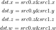
- ATOMAND (Atomic bitwise And)
Syntax: ATOMAND dst, resource, offset, src
Example: ATOMAND TEMP[0], RES[0], TEMP[1], TEMP[2]
The following operation is performed atomically on each component:
![dst_i = resource[offset]_i
resource[offset]_i = dst_i \& src_i](_images/math/6ac020a4ca1216fed093ff418455d1fa07337105.png)
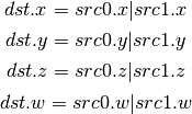
- ATOMOR (Atomic bitwise Or)
Syntax: ATOMOR dst, resource, offset, src
Example: ATOMOR TEMP[0], RES[0], TEMP[1], TEMP[2]
The following operation is performed atomically on each component:
![dst_i = resource[offset]_i
resource[offset]_i = dst_i | src_i](_images/math/9f339798d0e596ca38968828544c9e267cb76d45.png)
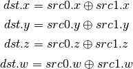
- ATOMXOR (Atomic bitwise Xor)
Syntax: ATOMXOR dst, resource, offset, src
Example: ATOMXOR TEMP[0], RES[0], TEMP[1], TEMP[2]
The following operation is performed atomically on each component:
![dst_i = resource[offset]_i
resource[offset]_i = dst_i \oplus src_i](_images/math/fc80f6fa107b3e82d94304da5e1873f137733d81.png)
- ATOMUMIN (Atomic unsigned minimum)
Syntax: ATOMUMIN dst, resource, offset, src
Example: ATOMUMIN TEMP[0], RES[0], TEMP[1], TEMP[2]
The following operation is performed atomically on each component:
![dst_i = resource[offset]_i
resource[offset]_i = (dst_i < src_i ? dst_i : src_i)](_images/math/aa1ef74f2d342f48f9c021ac64b929ade316cb06.png)
- ATOMUMAX (Atomic unsigned maximum)
Syntax: ATOMUMAX dst, resource, offset, src
Example: ATOMUMAX TEMP[0], RES[0], TEMP[1], TEMP[2]
The following operation is performed atomically on each component:
![dst_i = resource[offset]_i
resource[offset]_i = (dst_i > src_i ? dst_i : src_i)](_images/math/69de3f9536dd7b37a7eb599cd8b6b86fc72888cd.png)
- ATOMIMIN (Atomic signed minimum)
Syntax: ATOMIMIN dst, resource, offset, src
Example: ATOMIMIN TEMP[0], RES[0], TEMP[1], TEMP[2]
The following operation is performed atomically on each component:
- ATOMIMAX (Atomic signed maximum)
Syntax: ATOMIMAX dst, resource, offset, src
Example: ATOMIMAX TEMP[0], RES[0], TEMP[1], TEMP[2]
The following operation is performed atomically on each component:
Explanation of symbols used
Functions
Absolute value of x.
Ceiling of x.
- clamp(x,y,z) Clamp x between y and z.
- (x < y) ? y : (x > z) ? z : x
Floor of x.
Logarithm of x, base 2.
- max(x,y) Maximum of x and y.
- (x > y) ? x : y
- min(x,y) Minimum of x and y.
- (x < y) ? x : y
partialx(x) Derivative of x relative to fragment’s X.
partialy(x) Derivative of x relative to fragment’s Y.
pop() Pop from stack.
x to the power y.
push(x) Push x on stack.
round(x) Round x.
trunc(x) Truncate x, i.e. drop the fraction bits.
Keywords
discard Discard fragment.
pc Program counter.
target Label of target instruction.
Other tokens
Declaration
Declares a register that is will be referenced as an operand in Instruction tokens.
File field contains register file that is being declared and is one of TGSI_FILE.
UsageMask field specifies which of the register components can be accessed and is one of TGSI_WRITEMASK.
The Local flag specifies that a given value isn’t intended for subroutine parameter passing and, as a result, the implementation isn’t required to give any guarantees of it being preserved across subroutine boundaries. As it’s merely a compiler hint, the implementation is free to ignore it.
If Dimension flag is set to 1, a Declaration Dimension token follows.
If Semantic flag is set to 1, a Declaration Semantic token follows.
If Interpolate flag is set to 1, a Declaration Interpolate token follows.
If file is TGSI_FILE_RESOURCE, a Declaration Resource token follows.
If Array flag is set to 1, a Declaration Array token follows.
Array Declaration
Declarations can optional have an ArrayID attribute which can be referred by indirect addressing operands. An ArrayID of zero is reserved and treaded as if no ArrayID is specified.
If an indirect addressing operand refers to a specific declaration by using an ArrayID only the registers in this declaration are guaranteed to be accessed, accessing any register outside this declaration results in undefined behavior. Note that for compatibility the effective index is zero-based and not relative to the specified declaration
If no ArrayID is specified with an indirect addressing operand the whole register file might be accessed by this operand. This is strongly discouraged and will prevent packing of scalar/vec2 arrays and effective alias analysis.
Declaration Semantic
Vertex and fragment shader input and output registers may be labeled with semantic information consisting of a name and index.
Follows Declaration token if Semantic bit is set.
Since its purpose is to link a shader with other stages of the pipeline, it is valid to follow only those Declaration tokens that declare a register either in INPUT or OUTPUT file.
SemanticName field contains the semantic name of the register being declared. There is no default value.
SemanticIndex is an optional subscript that can be used to distinguish different register declarations with the same semantic name. The default value is 0.
The meanings of the individual semantic names are explained in the following sections.
TGSI_SEMANTIC_POSITION
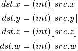
For vertex shaders, TGSI_SEMANTIC_POSITION indicates the vertex shader output register which contains the homogeneous vertex position in the clip space coordinate system. After clipping, the X, Y and Z components of the vertex will be divided by the W value to get normalized device coordinates.
For fragment shaders, TGSI_SEMANTIC_POSITION is used to indicate that fragment shader input contains the fragment’s window position. The X component starts at zero and always increases from left to right. The Y component starts at zero and always increases but Y=0 may either indicate the top of the window or the bottom depending on the fragment coordinate origin convention (see TGSI_PROPERTY_FS_COORD_ORIGIN). The Z coordinate ranges from 0 to 1 to represent depth from the front to the back of the Z buffer. The W component contains the interpolated reciprocal of the vertex position W component (corresponding to gl_Fragcoord, but unlike d3d10 which interpolates the same 1/w but then gives back the reciprocal of the interpolated value).
Fragment shaders may also declare an output register with TGSI_SEMANTIC_POSITION. Only the Z component is writable. This allows the fragment shader to change the fragment’s Z position.
TGSI_SEMANTIC_COLOR
For vertex shader outputs or fragment shader inputs/outputs, this label indicates that the resister contains an R,G,B,A color.
Several shader inputs/outputs may contain colors so the semantic index is used to distinguish them. For example, color[0] may be the diffuse color while color[1] may be the specular color.
This label is needed so that the flat/smooth shading can be applied to the right interpolants during rasterization.
TGSI_SEMANTIC_BCOLOR
Back-facing colors are only used for back-facing polygons, and are only valid in vertex shader outputs. After rasterization, all polygons are front-facing and COLOR and BCOLOR end up occupying the same slots in the fragment shader, so all BCOLORs effectively become regular COLORs in the fragment shader.
TGSI_SEMANTIC_FOG
Vertex shader inputs and outputs and fragment shader inputs may be labeled with TGSI_SEMANTIC_FOG to indicate that the register contains a fog coordinate. Typically, the fragment shader will use the fog coordinate to compute a fog blend factor which is used to blend the normal fragment color with a constant fog color. But fog coord really is just an ordinary vec4 register like regular semantics.
TGSI_SEMANTIC_PSIZE
Vertex shader input and output registers may be labeled with TGIS_SEMANTIC_PSIZE to indicate that the register contains a point size in the form (S, 0, 0, 1). The point size controls the width or diameter of points for rasterization. This label cannot be used in fragment shaders.
When using this semantic, be sure to set the appropriate state in the Rasterizer first.
TGSI_SEMANTIC_TEXCOORD
Only available if PIPE_CAP_TGSI_TEXCOORD is exposed !
Vertex shader outputs and fragment shader inputs may be labeled with this semantic to make them replaceable by sprite coordinates via the sprite_coord_enable state in the Rasterizer. The semantic index permitted with this semantic is limited to <= 7.
If the driver does not support TEXCOORD, sprite coordinate replacement applies to inputs with the GENERIC semantic instead.
The intended use case for this semantic is gl_TexCoord.
TGSI_SEMANTIC_PCOORD
Only available if PIPE_CAP_TGSI_TEXCOORD is exposed !
Fragment shader inputs may be labeled with TGSI_SEMANTIC_PCOORD to indicate that the register contains sprite coordinates in the form (x, y, 0, 1), if the current primitive is a point and point sprites are enabled. Otherwise, the contents of the register are undefined.
The intended use case for this semantic is gl_PointCoord.
TGSI_SEMANTIC_GENERIC
All vertex/fragment shader inputs/outputs not labeled with any other semantic label can be considered to be generic attributes. Typical uses of generic inputs/outputs are texcoords and user-defined values.
TGSI_SEMANTIC_NORMAL
Indicates that a vertex shader input is a normal vector. This is typically only used for legacy graphics APIs.
TGSI_SEMANTIC_FACE
This label applies to fragment shader inputs only and indicates that the register contains front/back-face information of the form (F, 0, 0, 1). The first component will be positive when the fragment belongs to a front-facing polygon, and negative when the fragment belongs to a back-facing polygon.
TGSI_SEMANTIC_EDGEFLAG
For vertex shaders, this sematic label indicates that an input or output is a boolean edge flag. The register layout is [F, x, x, x] where F is 0.0 or 1.0 and x = don’t care. Normally, the vertex shader simply copies the edge flag input to the edgeflag output.
Edge flags are used to control which lines or points are actually drawn when the polygon mode converts triangles/quads/polygons into points or lines.
TGSI_SEMANTIC_STENCIL
For fragment shaders, this semantic label indicates that an output is a writable stencil reference value. Only the Y component is writable. This allows the fragment shader to change the fragments stencilref value.
TGSI_SEMANTIC_VIEWPORT_INDEX
For geometry shaders, this semantic label indicates that an output contains the index of the viewport (and scissor) to use. This is an integer value, and only the X component is used.
TGSI_SEMANTIC_LAYER
For geometry shaders, this semantic label indicates that an output contains the layer value to use for the color and depth/stencil surfaces. This is an integer value, and only the X component is used. (Also known as rendertarget array index.)
TGSI_SEMANTIC_CULLDIST
Used as distance to plane for performing application-defined culling of individual primitives against a plane. When components of vertex elements are given this label, these values are assumed to be a float32 signed distance to a plane. Primitives will be completely discarded if the plane distance for all of the vertices in the primitive are < 0. If a vertex has a cull distance of NaN, that vertex counts as “out” (as if its < 0); The limits on both clip and cull distances are bound by the PIPE_MAX_CLIP_OR_CULL_DISTANCE_COUNT define which defines the maximum number of components that can be used to hold the distances and by the PIPE_MAX_CLIP_OR_CULL_DISTANCE_ELEMENT_COUNT which specifies the maximum number of registers which can be annotated with those semantics.
TGSI_SEMANTIC_CLIPDIST
When components of vertex elements are identified this way, these values are each assumed to be a float32 signed distance to a plane. Primitive setup only invokes rasterization on pixels for which the interpolated plane distances are >= 0. Multiple clip planes can be implemented simultaneously, by annotating multiple components of one or more vertex elements with the above specified semantic. The limits on both clip and cull distances are bound by the PIPE_MAX_CLIP_OR_CULL_DISTANCE_COUNT define which defines the maximum number of components that can be used to hold the distances and by the PIPE_MAX_CLIP_OR_CULL_DISTANCE_ELEMENT_COUNT which specifies the maximum number of registers which can be annotated with those semantics.
TGSI_SEMANTIC_SAMPLEID
For fragment shaders, this semantic label indicates that a system value contains the current sample id (i.e. gl_SampleID). This is an integer value, and only the X component is used.
TGSI_SEMANTIC_SAMPLEPOS
For fragment shaders, this semantic label indicates that a system value contains the current sample’s position (i.e. gl_SamplePosition). Only the X and Y values are used.
TGSI_SEMANTIC_SAMPLEMASK
For fragment shaders, this semantic label indicates that an output contains the sample mask used to disable further sample processing (i.e. gl_SampleMask). Only the X value is used, up to 32x MS.
TGSI_SEMANTIC_INVOCATIONID
For geometry shaders, this semantic label indicates that a system value contains the current invocation id (i.e. gl_InvocationID). This is an integer value, and only the X component is used.
TGSI_SEMANTIC_INSTANCEID
For vertex shaders, this semantic label indicates that a system value contains the current instance id (i.e. gl_InstanceID). It does not include the base instance. This is an integer value, and only the X component is used.
TGSI_SEMANTIC_VERTEXID
For vertex shaders, this semantic label indicates that a system value contains the current vertex id (i.e. gl_VertexID). It does (unlike in d3d10) include the base vertex. This is an integer value, and only the X component is used.
TGSI_SEMANTIC_VERTEXID_NOBASE
For vertex shaders, this semantic label indicates that a system value contains the current vertex id without including the base vertex (this corresponds to d3d10 vertex id, so TGSI_SEMANTIC_VERTEXID_NOBASE + TGSI_SEMANTIC_BASEVERTEX == TGSI_SEMANTIC_VERTEXID). This is an integer value, and only the X component is used.
TGSI_SEMANTIC_BASEVERTEX
For vertex shaders, this semantic label indicates that a system value contains the base vertex (i.e. gl_BaseVertex). Note that for non-indexed draw calls, this contains the first (or start) value instead. This is an integer value, and only the X component is used.
TGSI_SEMANTIC_PRIMID
For geometry and fragment shaders, this semantic label indicates the value contains the primitive id (i.e. gl_PrimitiveID). This is an integer value, and only the X component is used. FIXME: This right now can be either a ordinary input or a system value...
Declaration Interpolate
This token is only valid for fragment shader INPUT declarations.
The Interpolate field specifes the way input is being interpolated by the rasteriser and is one of TGSI_INTERPOLATE_*.
The Location field specifies the location inside the pixel that the interpolation should be done at, one of TGSI_INTERPOLATE_LOC_*. Note that when per-sample shading is enabled, the implementation may choose to interpolate at the sample irrespective of the Location field.
The CylindricalWrap bitfield specifies which register components should be subject to cylindrical wrapping when interpolating by the rasteriser. If TGSI_CYLINDRICAL_WRAP_X is set to 1, the X component should be interpolated according to cylindrical wrapping rules.
Declaration Sampler View
Follows Declaration token if file is TGSI_FILE_SAMPLER_VIEW.
DCL SVIEW[#], resource, type(s)
Declares a shader input sampler view and assigns it to a SVIEW[#] register.
resource can be one of BUFFER, 1D, 2D, 3D, 1DArray and 2DArray.
type must be 1 or 4 entries (if specifying on a per-component level) out of UNORM, SNORM, SINT, UINT and FLOAT.
Declaration Resource
Follows Declaration token if file is TGSI_FILE_RESOURCE.
DCL RES[#], resource [, WR] [, RAW]
Declares a shader input resource and assigns it to a RES[#] register.
resource can be one of BUFFER, 1D, 2D, 3D, CUBE, 1DArray and 2DArray.
If the RAW keyword is not specified, the texture data will be subject to conversion, swizzling and scaling as required to yield the specified data type from the physical data format of the bound resource.
If the RAW keyword is specified, no channel conversion will be performed: the values read for each of the channels (X,Y,Z,W) will correspond to consecutive words in the same order and format they’re found in memory. No element-to-address conversion will be performed either: the value of the provided X coordinate will be interpreted in byte units instead of texel units. The result of accessing a misaligned address is undefined.
Usage of the STORE opcode is only allowed if the WR (writable) flag is set.
Properties
Properties are general directives that apply to the whole TGSI program.
FS_COORD_ORIGIN
Specifies the fragment shader TGSI_SEMANTIC_POSITION coordinate origin. The default value is UPPER_LEFT.
If UPPER_LEFT, the position will be (0,0) at the upper left corner and increase downward and rightward. If LOWER_LEFT, the position will be (0,0) at the lower left corner and increase upward and rightward.
OpenGL defaults to LOWER_LEFT, and is configurable with the GL_ARB_fragment_coord_conventions extension.
DirectX 9/10 use UPPER_LEFT.
FS_COORD_PIXEL_CENTER
Specifies the fragment shader TGSI_SEMANTIC_POSITION pixel center convention. The default value is HALF_INTEGER.
If HALF_INTEGER, the fractionary part of the position will be 0.5 If INTEGER, the fractionary part of the position will be 0.0
Note that this does not affect the set of fragments generated by rasterization, which is instead controlled by half_pixel_center in the rasterizer.
OpenGL defaults to HALF_INTEGER, and is configurable with the GL_ARB_fragment_coord_conventions extension.
DirectX 9 uses INTEGER. DirectX 10 uses HALF_INTEGER.
FS_COLOR0_WRITES_ALL_CBUFS
Specifies that writes to the fragment shader color 0 are replicated to all bound cbufs. This facilitates OpenGL’s fragColor output vs fragData[0] where fragData is directed to a single color buffer, but fragColor is broadcast.
VS_PROHIBIT_UCPS
If this property is set on the program bound to the shader stage before the fragment shader, user clip planes should have no effect (be disabled) even if that shader does not write to any clip distance outputs and the rasterizer’s clip_plane_enable is non-zero. This property is only supported by drivers that also support shader clip distance outputs. This is useful for APIs that don’t have UCPs and where clip distances written by a shader cannot be disabled.
GS_INVOCATIONS
Specifies the number of times a geometry shader should be executed for each input primitive. Each invocation will have a different TGSI_SEMANTIC_INVOCATIONID system value set. If not specified, assumed to be 1.
VS_WINDOW_SPACE_POSITION
If this property is set on the vertex shader, the TGSI_SEMANTIC_POSITION output is assumed to contain window space coordinates. Division of X,Y,Z by W and the viewport transformation are disabled, and 1/W is directly taken from the 4-th component of the shader output. Naturally, clipping is not performed on window coordinates either. The effect of this property is undefined if a geometry or tessellation shader are in use.
Texture Sampling and Texture Formats
This table shows how texture image components are returned as (x,y,z,w) tuples by TGSI texture instructions, such as TEX, TXD, and TXP. For reference, OpenGL and Direct3D conventions are shown as well.
| Texture Components | Gallium | OpenGL | Direct3D 9 |
|---|---|---|---|
| R | (r, 0, 0, 1) | (r, 0, 0, 1) | (r, 1, 1, 1) |
| RG | (r, g, 0, 1) | (r, g, 0, 1) | (r, g, 1, 1) |
| RGB | (r, g, b, 1) | (r, g, b, 1) | (r, g, b, 1) |
| RGBA | (r, g, b, a) | (r, g, b, a) | (r, g, b, a) |
| A | (0, 0, 0, a) | (0, 0, 0, a) | (0, 0, 0, a) |
| L | (l, l, l, 1) | (l, l, l, 1) | (l, l, l, 1) |
| LA | (l, l, l, a) | (l, l, l, a) | (l, l, l, a) |
| I | (i, i, i, i) | (i, i, i, i) | N/A |
| UV | XXX TBD | (0, 0, 0, 1) [1] | (u, v, 1, 1) |
| Z | XXX TBD | (z, z, z, 1) [2] | (0, z, 0, 1) |
| S | (s, s, s, s) | unknown | unknown |
| [1] | http://www.opengl.org/registry/specs/ATI/envmap_bumpmap.txt |
| [2] | the default is (z, z, z, 1) but may also be (0, 0, 0, z) or (z, z, z, z) depending on the value of GL_DEPTH_TEXTURE_MODE. |
Screen
A screen is an object representing the context-independent part of a device.
Flags and enumerations
XXX some of these don’t belong in this section.
PIPE_CAP_*
Capability queries return information about the features and limits of the driver/GPU. For floating-point values, use get_paramf, and for boolean or integer values, use get_param.
The integer capabilities:
- PIPE_CAP_NPOT_TEXTURES: Whether NPOT textures may have repeat modes, normalized coordinates, and mipmaps.
- PIPE_CAP_TWO_SIDED_STENCIL: Whether the stencil test can also affect back-facing polygons.
- PIPE_CAP_MAX_DUAL_SOURCE_RENDER_TARGETS: How many dual-source blend RTs are support. Blend for more information.
- PIPE_CAP_ANISOTROPIC_FILTER: Whether textures can be filtered anisotropically.
- PIPE_CAP_POINT_SPRITE: Whether point sprites are available.
- PIPE_CAP_MAX_RENDER_TARGETS: The maximum number of render targets that may be bound.
- PIPE_CAP_OCCLUSION_QUERY: Whether occlusion queries are available.
- PIPE_CAP_QUERY_TIME_ELAPSED: Whether PIPE_QUERY_TIME_ELAPSED queries are available.
- PIPE_CAP_TEXTURE_SHADOW_MAP: indicates whether the fragment shader hardware can do the depth texture / Z comparison operation in TEX instructions for shadow testing.
- PIPE_CAP_TEXTURE_SWIZZLE: Whether swizzling through sampler views is supported.
- PIPE_CAP_MAX_TEXTURE_2D_LEVELS: The maximum number of mipmap levels available for a 2D texture.
- PIPE_CAP_MAX_TEXTURE_3D_LEVELS: The maximum number of mipmap levels available for a 3D texture.
- PIPE_CAP_MAX_TEXTURE_CUBE_LEVELS: The maximum number of mipmap levels available for a cubemap.
- PIPE_CAP_TEXTURE_MIRROR_CLAMP: Whether mirrored texture coordinates with clamp are supported.
- PIPE_CAP_BLEND_EQUATION_SEPARATE: Whether alpha blend equations may be different from color blend equations, in Blend state.
- PIPE_CAP_SM3: Whether the vertex shader and fragment shader support equivalent opcodes to the Shader Model 3 specification. XXX oh god this is horrible
- PIPE_CAP_MAX_STREAM_OUTPUT_BUFFERS: The maximum number of stream buffers.
- PIPE_CAP_PRIMITIVE_RESTART: Whether primitive restart is supported.
- PIPE_CAP_INDEP_BLEND_ENABLE: Whether per-rendertarget blend enabling and channel masks are supported. If 0, then the first rendertarget’s blend mask is replicated across all MRTs.
- PIPE_CAP_INDEP_BLEND_FUNC: Whether per-rendertarget blend functions are available. If 0, then the first rendertarget’s blend functions affect all MRTs.
- PIPE_CAP_MAX_TEXTURE_ARRAY_LAYERS: The maximum number of texture array layers supported. If 0, the array textures are not supported at all and the ARRAY texture targets are invalid.
- PIPE_CAP_TGSI_FS_COORD_ORIGIN_UPPER_LEFT: Whether the TGSI property FS_COORD_ORIGIN with value UPPER_LEFT is supported.
- PIPE_CAP_TGSI_FS_COORD_ORIGIN_LOWER_LEFT: Whether the TGSI property FS_COORD_ORIGIN with value LOWER_LEFT is supported.
- PIPE_CAP_TGSI_FS_COORD_PIXEL_CENTER_HALF_INTEGER: Whether the TGSI property FS_COORD_PIXEL_CENTER with value HALF_INTEGER is supported.
- PIPE_CAP_TGSI_FS_COORD_PIXEL_CENTER_INTEGER: Whether the TGSI property FS_COORD_PIXEL_CENTER with value INTEGER is supported.
- PIPE_CAP_DEPTH_CLIP_DISABLE: Whether the driver is capable of disabling depth clipping (through pipe_rasterizer_state)
- PIPE_CAP_SHADER_STENCIL_EXPORT: Whether a stencil reference value can be written from a fragment shader.
- PIPE_CAP_TGSI_INSTANCEID: Whether TGSI_SEMANTIC_INSTANCEID is supported in the vertex shader.
- PIPE_CAP_VERTEX_ELEMENT_INSTANCE_DIVISOR: Whether the driver supports per-instance vertex attribs.
- PIPE_CAP_FRAGMENT_COLOR_CLAMPED: Whether fragment color clamping is supported. That is, is the pipe_rasterizer_state::clamp_fragment_color flag supported by the driver? If not, the state tracker will insert clamping code into the fragment shaders when needed.
- PIPE_CAP_MIXED_COLORBUFFER_FORMATS: Whether mixed colorbuffer formats are supported, e.g. RGBA8 and RGBA32F as the first and second colorbuffer, resp.
- PIPE_CAP_VERTEX_COLOR_UNCLAMPED: Whether the driver is capable of outputting unclamped vertex colors from a vertex shader. If unsupported, the vertex colors are always clamped. This is the default for DX9 hardware.
- PIPE_CAP_VERTEX_COLOR_CLAMPED: Whether the driver is capable of clamping vertex colors when they come out of a vertex shader, as specified by the pipe_rasterizer_state::clamp_vertex_color flag. If unsupported, the vertex colors are never clamped. This is the default for DX10 hardware. If both clamped and unclamped CAPs are supported, the clamping can be controlled through pipe_rasterizer_state. If the driver cannot do vertex color clamping, the state tracker may insert clamping code into the vertex shader.
- PIPE_CAP_GLSL_FEATURE_LEVEL: Whether the driver supports features equivalent to a specific GLSL version. E.g. for GLSL 1.3, report 130.
- PIPE_CAP_QUADS_FOLLOW_PROVOKING_VERTEX_CONVENTION: Whether quads adhere to the flatshade_first setting in pipe_rasterizer_state.
- PIPE_CAP_USER_VERTEX_BUFFERS: Whether the driver supports user vertex buffers. If not, the state tracker must upload all data which is not in hw resources. If user-space buffers are supported, the driver must also still accept HW resource buffers.
- PIPE_CAP_VERTEX_BUFFER_OFFSET_4BYTE_ALIGNED_ONLY: This CAP describes a hw limitation. If true, pipe_vertex_buffer::buffer_offset must always be aligned to 4. If false, there are no restrictions on the offset.
- PIPE_CAP_VERTEX_BUFFER_STRIDE_4BYTE_ALIGNED_ONLY: This CAP describes a hw limitation. If true, pipe_vertex_buffer::stride must always be aligned to 4. If false, there are no restrictions on the stride.
- PIPE_CAP_VERTEX_ELEMENT_SRC_OFFSET_4BYTE_ALIGNED_ONLY: This CAP describes a hw limitation. If true, pipe_vertex_element::src_offset must always be aligned to 4. If false, there are no restrictions on src_offset.
- PIPE_CAP_COMPUTE: Whether the implementation supports the compute entry points defined in pipe_context and pipe_screen.
- PIPE_CAP_USER_INDEX_BUFFERS: Whether user index buffers are supported. If not, the state tracker must upload all indices which are not in hw resources. If user-space buffers are supported, the driver must also still accept HW resource buffers.
- PIPE_CAP_USER_CONSTANT_BUFFERS: Whether user-space constant buffers are supported. If not, the state tracker must put constants into HW resources/buffers. If user-space constant buffers are supported, the driver must still accept HW constant buffers also.
- PIPE_CAP_CONSTANT_BUFFER_OFFSET_ALIGNMENT: Describes the required alignment of pipe_constant_buffer::buffer_offset.
- PIPE_CAP_START_INSTANCE: Whether the driver supports pipe_draw_info::start_instance.
- PIPE_CAP_QUERY_TIMESTAMP: Whether PIPE_QUERY_TIMESTAMP and the pipe_screen::get_timestamp hook are implemented.
- PIPE_CAP_TEXTURE_MULTISAMPLE: Whether all MSAA resources supported for rendering are also supported for texturing.
- PIPE_CAP_MIN_MAP_BUFFER_ALIGNMENT: The minimum alignment that should be expected for a pointer returned by transfer_map if the resource is PIPE_BUFFER. In other words, the pointer returned by transfer_map is always aligned to this value.
- PIPE_CAP_TEXTURE_BUFFER_OFFSET_ALIGNMENT: Describes the required alignment for pipe_sampler_view::u.buf.first_element, in bytes. If a driver does not support first/last_element, it should return 0.
- PIPE_CAP_TGSI_TEXCOORD: This CAP describes a hw limitation. If true, the hardware cannot replace arbitrary shader inputs with sprite coordinates and hence the inputs that are desired to be replaceable must be declared with TGSI_SEMANTIC_TEXCOORD instead of TGSI_SEMANTIC_GENERIC. The rasterizer’s sprite_coord_enable state therefore also applies to the TEXCOORD semantic. Also, TGSI_SEMANTIC_PCOORD becomes available, which labels a fragment shader input that will always be replaced with sprite coordinates.
- PIPE_CAP_PREFER_BLIT_BASED_TEXTURE_TRANSFER: Whether it is preferable to use a blit to implement a texture transfer which needs format conversions and swizzling in state trackers. Generally, all hardware drivers with dedicated memory should return 1 and all software rasterizers should return 0.
- PIPE_CAP_QUERY_PIPELINE_STATISTICS: Whether PIPE_QUERY_PIPELINE_STATISTICS is supported.
- PIPE_CAP_TEXTURE_BORDER_COLOR_QUIRK: Bitmask indicating whether special considerations have to be given to the interaction between the border color in the sampler object and the sampler view used with it. If PIPE_QUIRK_TEXTURE_BORDER_COLOR_SWIZZLE_R600 is set, the border color may be affected in undefined ways for any kind of permutational swizzle (any swizzle XYZW where X/Y/Z/W are not ZERO, ONE, or R/G/B/A respectively) in the sampler view. If PIPE_QUIRK_TEXTURE_BORDER_COLOR_SWIZZLE_NV50 is set, the border color state should be swizzled manually according to the swizzle in the sampler view it is intended to be used with, or herein undefined results may occur for permutational swizzles.
- PIPE_CAP_MAX_TEXTURE_BUFFER_SIZE: The maximum accessible size with a buffer sampler view, in bytes.
- PIPE_CAP_MAX_VIEWPORTS: The maximum number of viewports (and scissors since they are linked) a driver can support. Returning 0 is equivalent to returning 1 because every driver has to support at least a single viewport/scissor combination.
- PIPE_CAP_ENDIANNESS:: The endianness of the device. Either PIPE_ENDIAN_BIG or PIPE_ENDIAN_LITTLE.
- PIPE_CAP_MIXED_FRAMEBUFFER_SIZES: Whether it is allowed to have different sizes for fb color/zs attachments. This controls whether ARB_framebuffer_object is provided.
- PIPE_CAP_TGSI_VS_LAYER_VIEWPORT: Whether TGSI_SEMANTIC_LAYER and TGSI_SEMANTIC_VIEWPORT_INDEX are supported as vertex shader outputs. Note that the viewport will only be used if multiple viewports are exposed.
- PIPE_CAP_MAX_GEOMETRY_OUTPUT_VERTICES: The maximum number of vertices output by a single invocation of a geometry shader.
- PIPE_CAP_MAX_GEOMETRY_TOTAL_OUTPUT_COMPONENTS: The maximum number of vertex components output by a single invocation of a geometry shader. This is the product of the number of attribute components per vertex and the number of output vertices.
- PIPE_CAP_MAX_TEXTURE_GATHER_COMPONENTS: Max number of components in format that texture gather can operate on. 1 == RED, ALPHA etc, 4 == All formats.
- PIPE_CAP_TEXTURE_GATHER_SM5: Whether the texture gather hardware implements the SM5 features, component selection, shadow comparison, and run-time offsets.
- PIPE_CAP_BUFFER_MAP_PERSISTENT_COHERENT: Whether PIPE_TRANSFER_PERSISTENT and PIPE_TRANSFER_COHERENT are supported for buffers.
- PIPE_CAP_TEXTURE_QUERY_LOD: Whether the LODQ instruction is supported.
- PIPE_CAP_MIN_TEXTURE_GATHER_OFFSET: The minimum offset that can be used in conjunction with a texture gather opcode.
- PIPE_CAP_MAX_TEXTURE_GATHER_OFFSET: The maximum offset that can be used in conjunction with a texture gather opcode.
- PIPE_CAP_SAMPLE_SHADING: Whether there is support for per-sample shading. The context->set_min_samples function will be expected to be implemented.
- PIPE_CAP_TEXTURE_GATHER_OFFSETS: Whether the TG4 instruction can accept 4 offsets.
- PIPE_CAP_TGSI_VS_WINDOW_SPACE_POSITION: Whether TGSI_PROPERTY_VS_WINDOW_SPACE_POSITION is supported, which disables clipping and viewport transformation.
- PIPE_CAP_MAX_VERTEX_STREAMS: The maximum number of vertex streams supported by the geometry shader. If stream-out is supported, this should be at least 1. If stream-out is not supported, this should be 0.
- PIPE_CAP_DRAW_INDIRECT: Whether the driver supports taking draw arguments { count, instance_count, start, index_bias } from a PIPE_BUFFER resource. See pipe_draw_info.
- PIPE_CAP_TGSI_FS_FINE_DERIVATIVE: Whether the fragment shader supports the FINE versions of DDX/DDY.
- PIPE_CAP_VENDOR_ID: The vendor ID of the underlying hardware. If it’s not available one should return 0xFFFFFFFF.
- PIPE_CAP_DEVICE_ID: The device ID (PCI ID) of the underlying hardware. 0xFFFFFFFF if not available.
- PIPE_CAP_ACCELERATED: Whether the renderer is hardware accelerated.
- PIPE_CAP_VIDEO_MEMORY: The amount of video memory in megabytes.
- PIPE_CAP_UMA: If the device has a unified memory architecture or on-card memory and GART.
- PIPE_CAP_CONDITIONAL_RENDER_INVERTED: Whether the driver supports inverted condition for conditional rendering.
- PIPE_CAP_MAX_VERTEX_ATTRIB_STRIDE: The maximum supported vertex stride.
- PIPE_CAP_SAMPLER_VIEW_TARGET: Whether the sampler view’s target can be different than the underlying resource’s, as permitted by ARB_texture_view. For example a 2d array texture may be reinterpreted as a cube (array) texture and vice-versa.
- PIPE_CAP_CLIP_HALFZ: Whether the driver supports the pipe_rasterizer_state::clip_halfz being set to true. This is required for enabling ARB_clip_control.
- PIPE_CAP_VERTEXID_NOBASE: If true, the driver only supports TGSI_SEMANTIC_VERTEXID_NOBASE (and not TGSI_SEMANTIC_VERTEXID). This means state trackers for APIs whose vertexIDs are offset by basevertex (such as GL) will need to lower TGSI_SEMANTIC_VERTEXID to TGSI_SEMANTIC_VERTEXID_NOBASE and TGSI_SEMANTIC_BASEVERTEX, so drivers setting this must handle both these semantics. Only relevant if geometry shaders are supported. (Currently not possible to query availability of these two semantics outside this, at least BASEVERTEX should be exposed separately too).
- PIPE_CAP_POLYGON_OFFSET_CLAMP: If true, the driver implements support for pipe_rasterizer_state::offset_clamp.
- PIPE_CAP_MULTISAMPLE_Z_RESOLVE: Whether the driver supports blitting a multisampled depth buffer into a single-sampled texture (or depth buffer). Only the first sampled should be copied.
- PIPE_CAP_RESOURCE_FROM_USER_MEMORY: Whether the driver can create a pipe_resource where an already-existing piece of (malloc’d) user memory is used as its backing storage. In other words, whether the driver can map existing user memory into the device address space for direct device access. The create function is pipe_screen::resource_from_user_memory. The address and size must be page-aligned.
PIPE_CAPF_*
The floating-point capabilities are:
- PIPE_CAPF_MAX_LINE_WIDTH: The maximum width of a regular line.
- PIPE_CAPF_MAX_LINE_WIDTH_AA: The maximum width of a smoothed line.
- PIPE_CAPF_MAX_POINT_WIDTH: The maximum width and height of a point.
- PIPE_CAPF_MAX_POINT_WIDTH_AA: The maximum width and height of a smoothed point.
- PIPE_CAPF_MAX_TEXTURE_ANISOTROPY: The maximum level of anisotropy that can be applied to anisotropically filtered textures.
- PIPE_CAPF_MAX_TEXTURE_LOD_BIAS: The maximum LOD bias that may be applied to filtered textures.
- PIPE_CAPF_GUARD_BAND_LEFT, PIPE_CAPF_GUARD_BAND_TOP, PIPE_CAPF_GUARD_BAND_RIGHT, PIPE_CAPF_GUARD_BAND_BOTTOM: TODO
PIPE_SHADER_CAP_*
These are per-shader-stage capabitity queries. Different shader stages may support different features.
- PIPE_SHADER_CAP_MAX_INSTRUCTIONS: The maximum number of instructions.
- PIPE_SHADER_CAP_MAX_ALU_INSTRUCTIONS: The maximum number of arithmetic instructions.
- PIPE_SHADER_CAP_MAX_TEX_INSTRUCTIONS: The maximum number of texture instructions.
- PIPE_SHADER_CAP_MAX_TEX_INDIRECTIONS: The maximum number of texture indirections.
- PIPE_SHADER_CAP_MAX_CONTROL_FLOW_DEPTH: The maximum nested control flow depth.
- PIPE_SHADER_CAP_MAX_INPUTS: The maximum number of input registers.
- PIPE_SHADER_CAP_MAX_OUTPUTS: The maximum number of output registers. This is valid for all shaders except the fragment shader.
- PIPE_SHADER_CAP_MAX_CONST_BUFFER_SIZE: The maximum size per constant buffer in bytes.
- PIPE_SHADER_CAP_MAX_CONST_BUFFERS: Maximum number of constant buffers that can be bound to any shader stage using set_constant_buffer. If 0 or 1, the pipe will only permit binding one constant buffer per shader, and the shaders will not permit two-dimensional access to constants.
If a value greater than 0 is returned, the driver can have multiple constant buffers bound to shader stages. The CONST register file can be accessed with two-dimensional indices, like in the example below.
DCL CONST[0][0..7] # declare first 8 vectors of constbuf 0 DCL CONST[3][0] # declare first vector of constbuf 3 MOV OUT[0], CONST[0][3] # copy vector 3 of constbuf 0
For backwards compatibility, one-dimensional access to CONST register file is still supported. In that case, the constbuf index is assumed to be 0.
- PIPE_SHADER_CAP_MAX_TEMPS: The maximum number of temporary registers.
- PIPE_SHADER_CAP_MAX_PREDS: The maximum number of predicate registers.
- PIPE_SHADER_CAP_TGSI_CONT_SUPPORTED: Whether the continue opcode is supported.
- PIPE_SHADER_CAP_INDIRECT_INPUT_ADDR: Whether indirect addressing of the input file is supported.
- PIPE_SHADER_CAP_INDIRECT_OUTPUT_ADDR: Whether indirect addressing of the output file is supported.
- PIPE_SHADER_CAP_INDIRECT_TEMP_ADDR: Whether indirect addressing of the temporary file is supported.
- PIPE_SHADER_CAP_INDIRECT_CONST_ADDR: Whether indirect addressing of the constant file is supported.
- PIPE_SHADER_CAP_SUBROUTINES: Whether subroutines are supported, i.e. BGNSUB, ENDSUB, CAL, and RET, including RET in the main block.
- PIPE_SHADER_CAP_INTEGERS: Whether integer opcodes are supported. If unsupported, only float opcodes are supported.
- PIPE_SHADER_CAP_MAX_TEXTURE_SAMPLERS: The maximum number of texture samplers.
- PIPE_SHADER_CAP_PREFERRED_IR: Preferred representation of the program. It should be one of the pipe_shader_ir enum values.
- PIPE_SHADER_CAP_MAX_SAMPLER_VIEWS: The maximum number of texture sampler views. Must not be lower than PIPE_SHADER_CAP_MAX_TEXTURE_SAMPLERS.
- PIPE_SHADER_CAP_DOUBLES: Whether double precision floating-point operations are supported.
- PIPE_SHADER_CAP_TGSI_DROUND_SUPPORTED: Whether double precision rounding is supported. If it is, DTRUNC/DCEIL/DFLR/DROUND opcodes may be used.
- PIPE_SHADER_CAP_TGSI_DFRACEXP_DLDEXP_SUPPORTED: Whether DFRACEXP and DLDEXP are supported.
- PIPE_SHADER_CAP_TGSI_FMA_SUPPORTED: Whether FMA and DFMA (doubles only) are supported.
PIPE_COMPUTE_CAP_*
Compute-specific capabilities. They can be queried using pipe_screen::get_compute_param.
- PIPE_COMPUTE_CAP_IR_TARGET: A description of the target of the form processor-arch-manufacturer-os that will be passed on to the compiler. This CAP is only relevant for drivers that specify PIPE_SHADER_IR_LLVM or PIPE_SHADER_IR_NATIVE for their preferred IR. Value type: null-terminated string.
- PIPE_COMPUTE_CAP_GRID_DIMENSION: Number of supported dimensions for grid and block coordinates. Value type: uint64_t.
- PIPE_COMPUTE_CAP_MAX_GRID_SIZE: Maximum grid size in block units. Value type: uint64_t [].
- PIPE_COMPUTE_CAP_MAX_BLOCK_SIZE: Maximum block size in thread units. Value type: uint64_t [].
- PIPE_COMPUTE_CAP_MAX_THREADS_PER_BLOCK: Maximum number of threads that a single block can contain. Value type: uint64_t. This may be less than the product of the components of MAX_BLOCK_SIZE and is usually limited by the number of threads that can be resident simultaneously on a compute unit.
- PIPE_COMPUTE_CAP_MAX_GLOBAL_SIZE: Maximum size of the GLOBAL resource. Value type: uint64_t.
- PIPE_COMPUTE_CAP_MAX_LOCAL_SIZE: Maximum size of the LOCAL resource. Value type: uint64_t.
- PIPE_COMPUTE_CAP_MAX_PRIVATE_SIZE: Maximum size of the PRIVATE resource. Value type: uint64_t.
- PIPE_COMPUTE_CAP_MAX_INPUT_SIZE: Maximum size of the INPUT resource. Value type: uint64_t.
- PIPE_COMPUTE_CAP_MAX_MEM_ALLOC_SIZE: Maximum size of a memory object allocation in bytes. Value type: uint64_t.
- PIPE_COMPUTE_CAP_MAX_CLOCK_FREQUENCY: Maximum frequency of the GPU clock in MHz. Value type: uint32_t
- PIPE_COMPUTE_CAP_MAX_COMPUTE_UNITS: Maximum number of compute units Value type: uint32_t
- PIPE_COMPUTE_CAP_IMAGES_SUPPORTED: Whether images are supported non-zero means yes, zero means no. Value type: uint32_t
PIPE_BIND_*
These flags indicate how a resource will be used and are specified at resource creation time. Resources may be used in different roles during their lifecycle. Bind flags are cumulative and may be combined to create a resource which can be used for multiple things. Depending on the pipe driver’s memory management and these bind flags, resources might be created and handled quite differently.
- PIPE_BIND_RENDER_TARGET: A color buffer or pixel buffer which will be rendered to. Any surface/resource attached to pipe_framebuffer_state::cbufs must have this flag set.
- PIPE_BIND_DEPTH_STENCIL: A depth (Z) buffer and/or stencil buffer. Any depth/stencil surface/resource attached to pipe_framebuffer_state::zsbuf must have this flag set.
- PIPE_BIND_BLENDABLE: Used in conjunction with PIPE_BIND_RENDER_TARGET to query whether a device supports blending for a given format. If this flag is set, surface creation may fail if blending is not supported for the specified format. If it is not set, a driver may choose to ignore blending on surfaces with formats that would require emulation.
- PIPE_BIND_DISPLAY_TARGET: A surface that can be presented to screen. Arguments to pipe_screen::flush_front_buffer must have this flag set.
- PIPE_BIND_SAMPLER_VIEW: A texture that may be sampled from in a fragment or vertex shader.
- PIPE_BIND_VERTEX_BUFFER: A vertex buffer.
- PIPE_BIND_INDEX_BUFFER: An vertex index/element buffer.
- PIPE_BIND_CONSTANT_BUFFER: A buffer of shader constants.
- PIPE_BIND_TRANSFER_WRITE: A transfer object which will be written to.
- PIPE_BIND_TRANSFER_READ: A transfer object which will be read from.
- PIPE_BIND_STREAM_OUTPUT: A stream output buffer.
- PIPE_BIND_CUSTOM:
- PIPE_BIND_SCANOUT: A front color buffer or scanout buffer.
- PIPE_BIND_SHARED: A sharable buffer that can be given to another process.
- PIPE_BIND_GLOBAL: A buffer that can be mapped into the global address space of a compute program.
- PIPE_BIND_SHADER_RESOURCE: A buffer or texture that can be bound to the graphics pipeline as a shader resource.
- PIPE_BIND_COMPUTE_RESOURCE: A buffer or texture that can be bound to the compute program as a shader resource.
- PIPE_BIND_COMMAND_ARGS_BUFFER: A buffer that may be sourced by the GPU command processor. It can contain, for example, the arguments to indirect draw calls.
PIPE_USAGE_*
The PIPE_USAGE enums are hints about the expected usage pattern of a resource. Note that drivers must always support read and write CPU access at any time no matter which hint they got.
- PIPE_USAGE_DEFAULT: Optimized for fast GPU access.
- PIPE_USAGE_IMMUTABLE: Optimized for fast GPU access and the resource is not expected to be mapped or changed (even by the GPU) after the first upload.
- PIPE_USAGE_DYNAMIC: Expect frequent write-only CPU access. What is uploaded is expected to be used at least several times by the GPU.
- PIPE_USAGE_STREAM: Expect frequent write-only CPU access. What is uploaded is expected to be used only once by the GPU.
- PIPE_USAGE_STAGING: Optimized for fast CPU access.
Methods
XXX to-do
get_name
Returns an identifying name for the screen.
get_vendor
Returns the screen vendor.
get_device_vendor
Returns the actual vendor of the device driving the screen (as opposed to the driver vendor).
context_create
Create a pipe_context.
priv is private data of the caller, which may be put to various unspecified uses, typically to do with implementing swapbuffers and/or front-buffer rendering.
is_format_supported
Determine if a resource in the given format can be used in a specific manner.
format the resource format
target one of the PIPE_TEXTURE_x flags
sample_count the number of samples. 0 and 1 mean no multisampling, the maximum allowed legal value is 32.
bindings is a bitmask of PIPE_BIND_* flags.
geom_flags is a bitmask of PIPE_TEXTURE_GEOM_x flags.
Returns TRUE if all usages can be satisfied.
can_create_resource
Check if a resource can actually be created (but don’t actually allocate any memory). This is used to implement OpenGL’s proxy textures. Typically, a driver will simply check if the total size of the given resource is less than some limit.
For PIPE_TEXTURE_CUBE, the pipe_resource::array_size field should be 6.
resource_create
Create a new resource from a template. The following fields of the pipe_resource must be specified in the template:
target one of the pipe_texture_target enums. Note that PIPE_BUFFER and PIPE_TEXTURE_X are not really fundamentally different. Modern APIs allow using buffers as shader resources.
format one of the pipe_format enums.
width0 the width of the base mip level of the texture or size of the buffer.
height0 the height of the base mip level of the texture (1 for 1D or 1D array textures).
depth0 the depth of the base mip level of the texture (1 for everything else).
array_size the array size for 1D and 2D array textures. For cube maps this must be 6, for other textures 1.
last_level the last mip map level present.
nr_samples the nr of msaa samples. 0 (or 1) specifies a resource which isn’t multisampled.
usage one of the PIPE_USAGE flags.
bind bitmask of the PIPE_BIND flags.
flags bitmask of PIPE_RESOURCE_FLAG flags.
resource_destroy
Destroy a resource. A resource is destroyed if it has no more references.
get_timestamp
Query a timestamp in nanoseconds. The returned value should match PIPE_QUERY_TIMESTAMP. This function returns immediately and doesn’t wait for rendering to complete (which cannot be achieved with queries).
get_driver_query_info
Return a driver-specific query. If the info parameter is NULL, the number of available queries is returned. Otherwise, the driver query at the specified index is returned in info. The function returns non-zero on success. The driver-specific query is described with the pipe_driver_query_info structure.
Resources and derived objects
Resources represent objects that hold data: textures and buffers.
They are mostly modelled after the resources in Direct3D 10/11, but with a different transfer/update mechanism, and more features for OpenGL support.
Resources can be used in several ways, and it is required to specify all planned uses through an appropriate set of bind flags.
TODO: write much more on resources
Transfers
Transfers are the mechanism used to access resources with the CPU.
OpenGL: OpenGL supports mapping buffers and has inline transfer functions for both buffers and textures
D3D11: D3D11 lacks transfers, but has special resource types that are mappable to the CPU address space
TODO: write much more on transfers
Resource targets
Resource targets determine the type of a resource.
Note that drivers may not actually have the restrictions listed regarding coordinate normalization and wrap modes, and in fact efficient OpenCL support will probably require drivers that don’t have any of them, which will probably be advertised with an appropriate cap.
TODO: document all targets. Note that both 3D and cube have restrictions that depend on the hardware generation.
PIPE_BUFFER
Buffer resource: can be used as a vertex, index, constant buffer (appropriate bind flags must be requested).
Buffers do not really have a format, it’s just bytes, but they are required to have their type set to a R8 format (without a specific “just byte” format, R8_UINT would probably make the most sense, but for historic reasons R8_UNORM is ok too). (This is just to make some shared buffer/texture code easier so format size can be queried.) width0 serves as size, most other resource properties don’t apply but must be set appropriately (depth0/height0/array_size must be 1, last_level 0).
They can be bound to stream output if supported. TODO: what about the restrictions lifted by the several later GL transform feedback extensions? How does one advertise that in Gallium?
They can be also be bound to a shader stage (for sampling) as usual by creating an appropriate sampler view, if the driver supports PIPE_CAP_TEXTURE_BUFFER_OBJECTS. This supports larger width than a 1d texture would (TODO limit currently unspecified, minimum must be at least 65536). Only the “direct fetch” sample opcodes are supported (TGSI_OPCODE_TXF, TGSI_OPCODE_SAMPLE_I) so the sampler state (coord wrapping etc.) is mostly ignored (with SAMPLE_I there’s no sampler state at all).
They can be also be bound to the framebuffer (only as color render target, not depth buffer, also there cannot be a depth buffer bound at the same time) as usual by creating an appropriate view (this is not usable in OpenGL). TODO there’s no CAP bit currently for this, there’s also unspecified size etc. limits TODO: is there any chance of supporting GL pixel buffer object acceleration with this?
OpenGL: vertex buffers in GL 1.5 or GL_ARB_vertex_buffer_object
- Binding to stream out requires GL 3.0 or GL_NV_transform_feedback
- Binding as constant buffers requires GL 3.1 or GL_ARB_uniform_buffer_object
- Binding to a sampling stage requires GL 3.1 or GL_ARB_texture_buffer_object
D3D11: buffer resources - Binding to a render target requires D3D_FEATURE_LEVEL_10_0
PIPE_TEXTURE_1D / PIPE_TEXTURE_1D_ARRAY
1D surface accessed with normalized coordinates. 1D array textures are supported depending on PIPE_CAP_MAX_TEXTURE_ARRAY_LAYERS.
- If PIPE_CAP_NPOT_TEXTURES is not supported,
width must be a power of two
height0 must be 1
depth0 must be 1
array_size must be 1 for PIPE_TEXTURE_1D
Mipmaps can be used
Must use normalized coordinates
OpenGL: GL_TEXTURE_1D in GL 1.0
- PIPE_CAP_NPOT_TEXTURES is equivalent to GL 2.0 or GL_ARB_texture_non_power_of_two
D3D11: 1D textures in D3D_FEATURE_LEVEL_10_0
PIPE_TEXTURE_RECT
2D surface with OpenGL GL_TEXTURE_RECTANGLE semantics.
- depth0 must be 1
- array_size must be 1
- last_level must be 0
- Must use unnormalized coordinates
- Must use a clamp wrap mode
OpenGL: GL_TEXTURE_RECTANGLE in GL 3.1 or GL_ARB_texture_rectangle or GL_NV_texture_rectangle
OpenCL: can create OpenCL images based on this, that can then be sampled arbitrarily
D3D11: not supported (only PIPE_TEXTURE_2D with normalized coordinates is supported)
PIPE_TEXTURE_2D / PIPE_TEXTURE_2D_ARRAY
2D surface accessed with normalized coordinates. 2D array textures are supported depending on PIPE_CAP_MAX_TEXTURE_ARRAY_LAYERS.
- If PIPE_CAP_NPOT_TEXTURES is not supported,
width and height must be powers of two
depth0 must be 1
array_size must be 1 for PIPE_TEXTURE_2D
Mipmaps can be used
Must use normalized coordinates
No special restrictions on wrap modes
OpenGL: GL_TEXTURE_2D in GL 1.0
- PIPE_CAP_NPOT_TEXTURES is equivalent to GL 2.0 or GL_ARB_texture_non_power_of_two
OpenCL: can create OpenCL images based on this, that can then be sampled arbitrarily
D3D11: 2D textures
- PIPE_CAP_NPOT_TEXTURES is equivalent to D3D_FEATURE_LEVEL_9_3
PIPE_TEXTURE_3D
3-dimensional array of texels. Mipmap dimensions are reduced in all 3 coordinates.
- If PIPE_CAP_NPOT_TEXTURES is not supported,
width, height and depth must be powers of two
array_size must be 1
Must use normalized coordinates
OpenGL: GL_TEXTURE_3D in GL 1.2 or GL_EXT_texture3D
- PIPE_CAP_NPOT_TEXTURES is equivalent to GL 2.0 or GL_ARB_texture_non_power_of_two
D3D11: 3D textures
- PIPE_CAP_NPOT_TEXTURES is equivalent to D3D_FEATURE_LEVEL_10_0
PIPE_TEXTURE_CUBE / PIPE_TEXTURE_CUBE_ARRAY
Cube maps consist of 6 2D faces. The 6 surfaces form an imaginary cube, and sampling happens by mapping an input 3-vector to the point of the cube surface in that direction. Cube map arrays are supported depending on PIPE_CAP_CUBE_MAP_ARRAY.
Sampling may be optionally seamless if a driver supports it (PIPE_CAP_SEAMLESS_CUBE_MAP), resulting in filtering taking samples from multiple surfaces near to the edge.
Width and height must be equal
depth0 must be 1
array_size must be a multiple of 6
- If PIPE_CAP_NPOT_TEXTURES is not supported,
width and height must be powers of two
Must use normalized coordinates
OpenGL: GL_TEXTURE_CUBE_MAP in GL 1.3 or EXT_texture_cube_map
- PIPE_CAP_NPOT_TEXTURES is equivalent to GL 2.0 or GL_ARB_texture_non_power_of_two
- Seamless cube maps require GL 3.2 or GL_ARB_seamless_cube_map or GL_AMD_seamless_cubemap_per_texture
- Cube map arrays require GL 4.0 or GL_ARB_texture_cube_map_array
D3D11: 2D array textures with the D3D11_RESOURCE_MISC_TEXTURECUBE flag
- PIPE_CAP_NPOT_TEXTURES is equivalent to D3D_FEATURE_LEVEL_10_0
- Cube map arrays require D3D_FEATURE_LEVEL_10_1
Surfaces
Surfaces are views of a resource that can be bound as a framebuffer to serve as the render target or depth buffer.
TODO: write much more on surfaces
OpenGL: FBOs are collections of surfaces in GL 3.0 or GL_ARB_framebuffer_object
D3D11: render target views and depth/stencil views
Sampler views
Sampler views are views of a resource that can be bound to a pipeline stage to be sampled from shaders.
TODO: write much more on sampler views
OpenGL: texture objects are actually sampler view and resource in a single unit
D3D11: shader resource views
Formats in gallium
Gallium format names mostly follow D3D10 conventions, with some extensions.
Format names like XnYnZnWn have the X component in the lowest-address n bits and the W component in the highest-address n bits; for B8G8R8A8, byte 0 is blue and byte 3 is alpha. Note that platform endianness is not considered in this definition. In C:
struct x8y8z8w8 { uint8_t x, y, z, w; };
Format aliases like XYZWstrq are (s+t+r+q)-bit integers in host endianness, with the X component in the s least-significant bits of the integer. In C:
uint32_t xyzw8888 = (x << 0) | (y << 8) | (z << 16) | (w << 24);
Format suffixes affect the interpretation of the channel:
- SINT: N bit signed integer [-2^(N-1) ... 2^(N-1) - 1]
- SNORM: N bit signed integer normalized to [-1 ... 1]
- SSCALED: N bit signed integer [-2^(N-1) ... 2^(N-1) - 1]
- FIXED: Signed fixed point integer, (N/2 - 1) bits of mantissa
- FLOAT: N bit IEEE754 float
- NORM: Normalized integers, signed or unsigned per channel
- UINT: N bit unsigned integer [0 ... 2^N - 1]
- UNORM: N bit unsigned integer normalized to [0 ... 1]
- USCALED: N bit unsigned integer [0 ... 2^N - 1]
The difference between SINT and SSCALED is that the former are pure integers in shaders, while the latter are floats; likewise for UINT versus USCALED.
There are two exceptions for FLOAT. R9G9B9E5_FLOAT is nine bits each of red green and blue mantissa, with a shared five bit exponent. R11G11B10_FLOAT is five bits of exponent and five or six bits of mantissa for each color channel.
For the NORM suffix, the signedness of each channel is indicated with an S or U after the number of channel bits, as in R5SG5SB6U_NORM.
The SRGB suffix is like UNORM in range, but in the sRGB colorspace.
Compressed formats are named first by the compression format string (DXT1, ETC1, etc), followed by a format-specific subtype. Refer to the appropriate compression spec for details.
Formats used in video playback are named by their FOURCC code.
Format names with an embedded underscore are subsampled. R8G8_B8G8 is a single 32-bit block of two pixels, where the R and B values are repeated in both pixels.
References
DirectX Graphics Infrastructure documentation on DXGI_FORMAT enum: http://msdn.microsoft.com/en-us/library/windows/desktop/bb173059%28v=vs.85%29.aspx
FOURCC codes for YUV formats: http://www.fourcc.org/yuv.php
Context
A Gallium rendering context encapsulates the state which effects 3D rendering such as blend state, depth/stencil state, texture samplers, etc.
Note that resource/texture allocation is not per-context but per-screen.
Methods
CSO State
All Constant State Object (CSO) state is created, bound, and destroyed, with triplets of methods that all follow a specific naming scheme. For example, create_blend_state, bind_blend_state, and destroy_blend_state.
CSO objects handled by the context object:
- Blend: *_blend_state
- Sampler: Texture sampler states are bound separately for fragment, vertex, geometry and compute shaders with the bind_sampler_states function. The start and num_samplers parameters indicate a range of samplers to change. NOTE: at this time, start is always zero and the CSO module will always replace all samplers at once (no sub-ranges). This may change in the future.
- Rasterizer: *_rasterizer_state
- Depth, Stencil, & Alpha: *_depth_stencil_alpha_state
- Shader: These are create, bind and destroy methods for vertex, fragment and geometry shaders.
- Vertex Elements: *_vertex_elements_state
Resource Binding State
This state describes how resources in various flavours (textures, buffers, surfaces) are bound to the driver.
- set_constant_buffer sets a constant buffer to be used for a given shader type. index is used to indicate which buffer to set (some apis may allow multiple ones to be set, and binding a specific one later, though drivers are mostly restricted to the first one right now).
- set_framebuffer_state
- set_vertex_buffers
- set_index_buffer
Non-CSO State
These pieces of state are too small, variable, and/or trivial to have CSO objects. They all follow simple, one-method binding calls, e.g. set_blend_color.
- set_stencil_ref sets the stencil front and back reference values which are used as comparison values in stencil test.
- set_blend_color
- set_sample_mask
- set_min_samples sets the minimum number of samples that must be run.
- set_clip_state
- set_polygon_stipple
- set_scissor_states sets the bounds for the scissor test, which culls pixels before blending to render targets. If the Rasterizer does not have the scissor test enabled, then the scissor bounds never need to be set since they will not be used. Note that scissor xmin and ymin are inclusive, but xmax and ymax are exclusive. The inclusive ranges in x and y would be [xmin..xmax-1] and [ymin..ymax-1]. The number of scissors should be the same as the number of set viewports and can be up to PIPE_MAX_VIEWPORTS.
- set_viewport_states
Sampler Views
These are the means to bind textures to shader stages. To create one, specify its format, swizzle and LOD range in sampler view template.
If texture format is different than template format, it is said the texture is being cast to another format. Casting can be done only between compatible formats, that is formats that have matching component order and sizes.
Swizzle fields specify they way in which fetched texel components are placed in the result register. For example, swizzle_r specifies what is going to be placed in first component of result register.
The first_level and last_level fields of sampler view template specify the LOD range the texture is going to be constrained to. Note that these values are in addition to the respective min_lod, max_lod values in the pipe_sampler_state (that is if min_lod is 2.0, and first_level 3, the first mip level used for sampling from the resource is effectively the fifth).
The first_layer and last_layer fields specify the layer range the texture is going to be constrained to. Similar to the LOD range, this is added to the array index which is used for sampling.
- set_sampler_views binds an array of sampler views to a shader stage. Every binding point acquires a reference to a respective sampler view and releases a reference to the previous sampler view.
- create_sampler_view creates a new sampler view. texture is associated with the sampler view which results in sampler view holding a reference to the texture. Format specified in template must be compatible with texture format.
- sampler_view_destroy destroys a sampler view and releases its reference to associated texture.
Shader Resources
Shader resources are textures or buffers that may be read or written from a shader without an associated sampler. This means that they have no support for floating point coordinates, address wrap modes or filtering.
Shader resources are specified for all the shader stages at once using the set_shader_resources method. When binding texture resources, the level, first_layer and last_layer pipe_surface fields specify the mipmap level and the range of layers the texture will be constrained to. In the case of buffers, first_element and last_element specify the range within the buffer that will be used by the shader resource. Writes to a shader resource are only allowed when the writable flag is set.
Surfaces
These are the means to use resources as color render targets or depthstencil attachments. To create one, specify the mip level, the range of layers, and the bind flags (either PIPE_BIND_DEPTH_STENCIL or PIPE_BIND_RENDER_TARGET). Note that layer values are in addition to what is indicated by the geometry shader output variable XXX_FIXME (that is if first_layer is 3 and geometry shader indicates index 2, the 5th layer of the resource will be used). These first_layer and last_layer parameters will only be used for 1d array, 2d array, cube, and 3d textures otherwise they are 0.
- create_surface creates a new surface.
- surface_destroy destroys a surface and releases its reference to the associated resource.
Stream output targets
Stream output, also known as transform feedback, allows writing the primitives produced by the vertex pipeline to buffers. This is done after the geometry shader or vertex shader if no geometry shader is present.
The stream output targets are views into buffer resources which can be bound as stream outputs and specify a memory range where it’s valid to write primitives. The pipe driver must implement memory protection such that any primitives written outside of the specified memory range are discarded.
Two stream output targets can use the same resource at the same time, but with a disjoint memory range.
Additionally, the stream output target internally maintains the offset into the buffer which is incremented everytime something is written to it. The internal offset is equal to how much data has already been written. It can be stored in device memory and the CPU actually doesn’t have to query it.
The stream output target can be used in a draw command to provide the vertex count. The vertex count is derived from the internal offset discussed above.
- create_stream_output_target create a new target.
- stream_output_target_destroy destroys a target. Users of this should use pipe_so_target_reference instead.
- set_stream_output_targets binds stream output targets. The parameter offset is an array which specifies the internal offset of the buffer. The internal offset is, besides writing, used for reading the data during the draw_auto stage, i.e. it specifies how much data there is in the buffer for the purposes of the draw_auto stage. -1 means the buffer should be appended to, and everything else sets the internal offset.
NOTE: The currently-bound vertex or geometry shader must be compiled with the properly-filled-in structure pipe_stream_output_info describing which outputs should be written to buffers and how. The structure is part of pipe_shader_state.
Clearing
Clear is one of the most difficult concepts to nail down to a single interface (due to both different requirements from APIs and also driver/hw specific differences).
clear initializes some or all of the surfaces currently bound to the framebuffer to particular RGBA, depth, or stencil values. Currently, this does not take into account color or stencil write masks (as used by GL), and always clears the whole surfaces (no scissoring as used by GL clear or explicit rectangles like d3d9 uses). It can, however, also clear only depth or stencil in a combined depth/stencil surface. If a surface includes several layers then all layers will be cleared.
clear_render_target clears a single color rendertarget with the specified color value. While it is only possible to clear one surface at a time (which can include several layers), this surface need not be bound to the framebuffer.
clear_depth_stencil clears a single depth, stencil or depth/stencil surface with the specified depth and stencil values (for combined depth/stencil buffers, is is also possible to only clear one or the other part). While it is only possible to clear one surface at a time (which can include several layers), this surface need not be bound to the framebuffer.
clear_buffer clears a PIPE_BUFFER resource with the specified clear value (which may be multiple bytes in length). Logically this is a memset with a multi-byte element value starting at offset bytes from resource start, going for size bytes. It is guaranteed that size % clear_value_size == 0.
Drawing
draw_vbo draws a specified primitive. The primitive mode and other properties are described by pipe_draw_info.
The mode, start, and count fields of pipe_draw_info specify the the mode of the primitive and the vertices to be fetched, in the range between start to start``+``count-1, inclusive.
Every instance with instanceID in the range between start_instance and start_instance``+``instance_count-1, inclusive, will be drawn.
If there is an index buffer bound, and indexed field is true, all vertex indices will be looked up in the index buffer.
In indexed draw, min_index and max_index respectively provide a lower and upper bound of the indices contained in the index buffer inside the range between start to start``+``count-1. This allows the driver to determine which subset of vertices will be referenced during te draw call without having to scan the index buffer. Providing a over-estimation of the the true bounds, for example, a min_index and max_index of 0 and 0xffffffff respectively, must give exactly the same rendering, albeit with less performance due to unreferenced vertex buffers being unnecessarily DMA’ed or processed. Providing a underestimation of the true bounds will result in undefined behavior, but should not result in program or system failure.
In case of non-indexed draw, min_index should be set to start and max_index should be set to start``+``count-1.
index_bias is a value added to every vertex index after lookup and before fetching vertex attributes.
When drawing indexed primitives, the primitive restart index can be used to draw disjoint primitive strips. For example, several separate line strips can be drawn by designating a special index value as the restart index. The primitive_restart flag enables/disables this feature. The restart_index field specifies the restart index value.
When primitive restart is in use, array indexes are compared to the restart index before adding the index_bias offset.
If a given vertex element has instance_divisor set to 0, it is said it contains per-vertex data and effective vertex attribute address needs to be recalculated for every index.
attribAddr = stride * index + src_offset
If a given vertex element has instance_divisor set to non-zero, it is said it contains per-instance data and effective vertex attribute address needs to recalculated for every instance_divisor-th instance.
attribAddr = stride * instanceID / instance_divisor + src_offset
In the above formulas, src_offset is taken from the given vertex element and stride is taken from a vertex buffer associated with the given vertex element.
The calculated attribAddr is used as an offset into the vertex buffer to fetch the attribute data.
The value of instanceID can be read in a vertex shader through a system value register declared with INSTANCEID semantic name.
Queries
Queries gather some statistic from the 3D pipeline over one or more draws. Queries may be nested, though not all state trackers exercise this.
Queries can be created with create_query and deleted with destroy_query. To start a query, use begin_query, and when finished, use end_query to end the query.
create_query takes a query type (PIPE_QUERY_*), as well as an index, which is the vertex stream for PIPE_QUERY_PRIMITIVES_GENERATED and PIPE_QUERY_PRIMITIVES_EMITTED, and allocates a query structure.
begin_query will clear/reset previous query results.
get_query_result is used to retrieve the results of a query. If the wait parameter is TRUE, then the get_query_result call will block until the results of the query are ready (and TRUE will be returned). Otherwise, if the wait parameter is FALSE, the call will not block and the return value will be TRUE if the query has completed or FALSE otherwise.
The interface currently includes the following types of queries:
PIPE_QUERY_OCCLUSION_COUNTER counts the number of fragments which are written to the framebuffer without being culled by Depth, Stencil, & Alpha testing or shader KILL instructions. The result is an unsigned 64-bit integer. This query can be used with render_condition.
In cases where a boolean result of an occlusion query is enough, PIPE_QUERY_OCCLUSION_PREDICATE should be used. It is just like PIPE_QUERY_OCCLUSION_COUNTER except that the result is a boolean value of FALSE for cases where COUNTER would result in 0 and TRUE for all other cases. This query can be used with render_condition.
PIPE_QUERY_TIME_ELAPSED returns the amount of time, in nanoseconds, the context takes to perform operations. The result is an unsigned 64-bit integer.
PIPE_QUERY_TIMESTAMP returns a device/driver internal timestamp, scaled to nanoseconds, recorded after all commands issued prior to end_query have been processed. This query does not require a call to begin_query. The result is an unsigned 64-bit integer.
PIPE_QUERY_TIMESTAMP_DISJOINT can be used to check the internal timer resolution and whether the timestamp counter has become unreliable due to things like throttling etc. - only if this is FALSE a timestamp query (within the timestamp_disjoint query) should be trusted. The result is a 64-bit integer specifying the timer resolution in Hz, followed by a boolean value indicating whether the timestamp counter is discontinuous or disjoint.
PIPE_QUERY_PRIMITIVES_GENERATED returns a 64-bit integer indicating the number of primitives processed by the pipeline (regardless of whether stream output is active or not).
PIPE_QUERY_PRIMITIVES_EMITTED returns a 64-bit integer indicating the number of primitives written to stream output buffers.
PIPE_QUERY_SO_STATISTICS returns 2 64-bit integers corresponding to the result of PIPE_QUERY_PRIMITIVES_EMITTED and the number of primitives that would have been written to stream output buffers if they had infinite space available (primitives_storage_needed), in this order. XXX the 2nd value is equivalent to PIPE_QUERY_PRIMITIVES_GENERATED but it is unclear if it should be increased if stream output is not active.
PIPE_QUERY_SO_OVERFLOW_PREDICATE returns a boolean value indicating whether the stream output targets have overflowed as a result of the commands issued between begin_query and end_query. This query can be used with render_condition.
PIPE_QUERY_GPU_FINISHED returns a boolean value indicating whether all commands issued before end_query have completed. However, this does not imply serialization. This query does not require a call to begin_query.
PIPE_QUERY_PIPELINE_STATISTICS returns an array of the following 64-bit integers: Number of vertices read from vertex buffers. Number of primitives read from vertex buffers. Number of vertex shader threads launched. Number of geometry shader threads launched. Number of primitives generated by geometry shaders. Number of primitives forwarded to the rasterizer. Number of primitives rasterized. Number of fragment shader threads launched. Number of tessellation control shader threads launched. Number of tessellation evaluation shader threads launched. If a shader type is not supported by the device/driver, the corresponding values should be set to 0.
Gallium does not guarantee the availability of any query types; one must always check the capabilities of the Screen first.
Conditional Rendering
A drawing command can be skipped depending on the outcome of a query (typically an occlusion query, or streamout overflow predicate). The render_condition function specifies the query which should be checked prior to rendering anything. Functions always honoring render_condition include (and are limited to) draw_vbo, clear, clear_render_target, clear_depth_stencil. The blit function (but not resource_copy_region, which seems inconsistent) can also optionally honor the current render condition.
If render_condition is called with query = NULL, conditional rendering is disabled and drawing takes place normally.
If render_condition is called with a non-null query subsequent drawing commands will be predicated on the outcome of the query. Commands will be skipped if condition is equal to the predicate result (for non-boolean queries such as OCCLUSION_QUERY, zero counts as FALSE, non-zero as TRUE).
If mode is PIPE_RENDER_COND_WAIT the driver will wait for the query to complete before deciding whether to render.
If mode is PIPE_RENDER_COND_NO_WAIT and the query has not yet completed, the drawing command will be executed normally. If the query has completed, drawing will be predicated on the outcome of the query.
If mode is PIPE_RENDER_COND_BY_REGION_WAIT or PIPE_RENDER_COND_BY_REGION_NO_WAIT rendering will be predicated as above for the non-REGION modes but in the case that an occlusion query returns a non-zero result, regions which were occluded may be ommitted by subsequent drawing commands. This can result in better performance with some GPUs. Normally, if the occlusion query returned a non-zero result subsequent drawing happens normally so fragments may be generated, shaded and processed even where they’re known to be obscured.
Flushing
flush
flush_resource
Flush the resource cache, so that the resource can be used by an external client. Possible usage: - flushing a resource before presenting it on the screen - flushing a resource if some other process or device wants to use it This shouldn’t be used to flush caches if the resource is only managed by a single pipe_screen and is not shared with another process. (i.e. you shouldn’t use it to flush caches explicitly if you want to e.g. use the resource for texturing)
Resource Busy Queries
is_resource_referenced
Blitting
These methods emulate classic blitter controls.
These methods operate directly on pipe_resource objects, and stand apart from any 3D state in the context. Blitting functionality may be moved to a separate abstraction at some point in the future.
resource_copy_region blits a region of a resource to a region of another resource, provided that both resources have the same format, or compatible formats, i.e., formats for which copying the bytes from the source resource unmodified to the destination resource will achieve the same effect of a textured quad blitter.. The source and destination may be the same resource, but overlapping blits are not permitted. This can be considered the equivalent of a CPU memcpy.
blit blits a region of a resource to a region of another resource, including scaling, format conversion, and up-/downsampling, as well as a destination clip rectangle (scissors). It can also optionally honor the current render condition (but either way the blit itself never contributes anything to queries currently gathering data). As opposed to manually drawing a textured quad, this lets the pipe driver choose the optimal method for blitting (like using a special 2D engine), and usually offers, for example, accelerated stencil-only copies even where PIPE_CAP_SHADER_STENCIL_EXPORT is not available.
Transfers
These methods are used to get data to/from a resource.
transfer_map creates a memory mapping and the transfer object associated with it. The returned pointer points to the start of the mapped range according to the box region, not the beginning of the resource. If transfer_map fails, the returned pointer to the buffer memory is NULL, and the pointer to the transfer object remains unchanged (i.e. it can be non-NULL).
transfer_unmap remove the memory mapping for and destroy the transfer object. The pointer into the resource should be considered invalid and discarded.
transfer_inline_write performs a simplified transfer for simple writes. Basically transfer_map, data write, and transfer_unmap all in one.
The box parameter to some of these functions defines a 1D, 2D or 3D region of pixels. This is self-explanatory for 1D, 2D and 3D texture targets.
For PIPE_TEXTURE_1D_ARRAY and PIPE_TEXTURE_2D_ARRAY, the box::z and box::depth fields refer to the array dimension of the texture.
For PIPE_TEXTURE_CUBE, the box:z and box::depth fields refer to the faces of the cube map (z + depth <= 6).
For PIPE_TEXTURE_CUBE_ARRAY, the box:z and box::depth fields refer to both the face and array dimension of the texture (face = z % 6, array = z / 6).
transfer_flush_region
If a transfer was created with FLUSH_EXPLICIT, it will not automatically be flushed on write or unmap. Flushes must be requested with transfer_flush_region. Flush ranges are relative to the mapped range, not the beginning of the resource.
texture_barrier
This function flushes all pending writes to the currently-set surfaces and invalidates all read caches of the currently-set samplers.
memory_barrier
This function flushes caches according to which of the PIPE_BARRIER_* flags are set.
PIPE_TRANSFER
These flags control the behavior of a transfer object.
- PIPE_TRANSFER_READ
- Resource contents read back (or accessed directly) at transfer create time.
- PIPE_TRANSFER_WRITE
- Resource contents will be written back at transfer_unmap time (or modified as a result of being accessed directly).
- PIPE_TRANSFER_MAP_DIRECTLY
- a transfer should directly map the resource. May return NULL if not supported.
- PIPE_TRANSFER_DISCARD_RANGE
- The memory within the mapped region is discarded. Cannot be used with PIPE_TRANSFER_READ.
- PIPE_TRANSFER_DISCARD_WHOLE_RESOURCE
- Discards all memory backing the resource. It should not be used with PIPE_TRANSFER_READ.
- PIPE_TRANSFER_DONTBLOCK
- Fail if the resource cannot be mapped immediately.
- PIPE_TRANSFER_UNSYNCHRONIZED
- Do not synchronize pending operations on the resource when mapping. The interaction of any writes to the map and any operations pending on the resource are undefined. Cannot be used with PIPE_TRANSFER_READ.
- PIPE_TRANSFER_FLUSH_EXPLICIT
- Written ranges will be notified later with transfer_flush_region. Cannot be used with PIPE_TRANSFER_READ.
- PIPE_TRANSFER_PERSISTENT
- Allows the resource to be used for rendering while mapped. PIPE_RESOURCE_FLAG_MAP_PERSISTENT must be set when creating the resource. If COHERENT is not set, memory_barrier(PIPE_BARRIER_MAPPED_BUFFER) must be called to ensure the device can see what the CPU has written.
- PIPE_TRANSFER_COHERENT
- If PERSISTENT is set, this ensures any writes done by the device are immediately visible to the CPU and vice versa. PIPE_RESOURCE_FLAG_MAP_COHERENT must be set when creating the resource.
Compute kernel execution
A compute program can be defined, bound or destroyed using create_compute_state, bind_compute_state or destroy_compute_state respectively.
Any of the subroutines contained within the compute program can be executed on the device using the launch_grid method. This method will execute as many instances of the program as elements in the specified N-dimensional grid, hopefully in parallel.
The compute program has access to four special resources:
- GLOBAL represents a memory space shared among all the threads running on the device. An arbitrary buffer created with the PIPE_BIND_GLOBAL flag can be mapped into it using the set_global_binding method.
- LOCAL represents a memory space shared among all the threads running in the same working group. The initial contents of this resource are undefined.
- PRIVATE represents a memory space local to a single thread. The initial contents of this resource are undefined.
- INPUT represents a read-only memory space that can be initialized at launch_grid time.
These resources use a byte-based addressing scheme, and they can be accessed from the compute program by means of the LOAD/STORE TGSI opcodes. Additional resources to be accessed using the same opcodes may be specified by the user with the set_compute_resources method.
In addition, normal texture sampling is allowed from the compute program: bind_sampler_states may be used to set up texture samplers for the compute stage and set_sampler_views may be used to bind a number of sampler views to it.
CSO
CSO, Constant State Objects, are a core part of Gallium’s API.
CSO work on the principle of reusable state; they are created by filling out a state object with the desired properties, then passing that object to a context. The context returns an opaque context-specific handle which can be bound at any time for the desired effect.
Blend
This state controls blending of the final fragments into the target rendering buffers.
Blend Factors
The blend factors largely follow the same pattern as their counterparts in other modern and legacy drawing APIs.
Dual source blend factors are supported for up to 1 MRT, although you can advertise > 1 MRT, the stack cannot handle them for a few reasons. There is no definition on how the 1D array of shader outputs should be mapped to something that would be a 2D array (location, index). No current hardware exposes > 1 MRT, and we should revisit this issue if anyone ever does.
Logical Operations
Logical operations, also known as logicops, lops, or rops, are supported. Only two-operand logicops are available. When logicops are enabled, all other blend state is ignored, including per-render-target state, so logicops are performed on all render targets.
Warning
The blend_enable flag is ignored for all render targets when logical operations are enabled.
For a source component s and destination component d, the logical operations are defined as taking the bits of each channel of each component, and performing one of the following operations per-channel:
- CLEAR: 0
- NOR:

- AND_INVERTED:

- COPY_INVERTED:

- AND_REVERSE:

- INVERT:

- XOR:

- NAND:

- AND:

- EQUIV:

- NOOP:

- OR_INVERTED:

- COPY:

- OR_REVERSE:

- OR:

- SET: 1
Note
The logical operation names and definitions match those of the OpenGL API, and are similar to the ROP2 and ROP3 definitions of GDI. This is intentional, to ease transitions to Gallium.
Members
These members affect all render targets.
dither
Whether dithering is enabled.
Note
Dithering is completely implementation-dependent. It may be ignored by drivers for any reason, and some render targets may always or never be dithered depending on their format or usage flags.
logicop_enable
Whether the blender should perform a logicop instead of blending.
logicop_func
The logicop to use. One of PIPE_LOGICOP.
- independent_blend_enable
- If enabled, blend state is different for each render target, and for each render target set in the respective member of the rt array. If disabled, blend state is the same for all render targets, and only the first member of the rt array contains valid data.
- rt
- Contains the per-rendertarget blend state.
Per-rendertarget Members
- blend_enable
- If blending is enabled, perform a blend calculation according to blend functions and source/destination factors. Otherwise, the incoming fragment color gets passed unmodified (but colormask still applies).
- rgb_func
- The blend function to use for rgb channels. One of PIPE_BLEND.
- rgb_src_factor
- The blend source factor to use for rgb channels. One of PIPE_BLENDFACTOR.
- rgb_dst_factor
- The blend destination factor to use for rgb channels. One of PIPE_BLENDFACTOR.
- alpha_func
- The blend function to use for the alpha channel. One of PIPE_BLEND.
- alpha_src_factor
- The blend source factor to use for the alpha channel. One of PIPE_BLENDFACTOR.
- alpha_dst_factor
- The blend destination factor to use for alpha channel. One of PIPE_BLENDFACTOR.
- colormask
- Bitmask of which channels to write. Combination of PIPE_MASK bits.
Depth, Stencil, & Alpha
These three states control the depth, stencil, and alpha tests, used to discard fragments that have passed through the fragment shader.
Traditionally, these three tests have been clumped together in hardware, so they are all stored in one structure.
During actual execution, the order of operations done on fragments is always:
- Alpha
- Stencil
- Depth
Depth Members
- enabled
- Whether the depth test is enabled.
- writemask
- Whether the depth buffer receives depth writes.
- func
- The depth test function. One of PIPE_FUNC.
Stencil Members
- enabled
- Whether the stencil test is enabled. For the second stencil, whether the two-sided stencil is enabled. If two-sided stencil is disabled, the other fields for the second array member are not valid.
- func
- The stencil test function. One of PIPE_FUNC.
- valuemask
- Stencil test value mask; this is ANDed with the value in the stencil buffer and the reference value before doing the stencil comparison test.
- writemask
- Stencil test writemask; this controls which bits of the stencil buffer are written.
- fail_op
- The operation to carry out if the stencil test fails. One of PIPE_STENCIL_OP.
- zfail_op
- The operation to carry out if the stencil test passes but the depth test fails. One of PIPE_STENCIL_OP.
- zpass_op
- The operation to carry out if the stencil test and depth test both pass. One of PIPE_STENCIL_OP.
Alpha Members
- enabled
- Whether the alpha test is enabled.
- func
- The alpha test function. One of PIPE_FUNC.
- ref_value
- Alpha test reference value; used for certain functions.
Rasterizer
The rasterizer state controls the rendering of points, lines and triangles. Attributes include polygon culling state, line width, line stipple, multisample state, scissoring and flat/smooth shading.
Linkage
clamp_vertex_color
If set, TGSI_SEMANTIC_COLOR registers are clamped to the [0, 1] range after the execution of the vertex shader, before being passed to the geometry shader or fragment shader.
OpenGL: glClampColor(GL_CLAMP_VERTEX_COLOR) in GL 3.0 or GL_ARB_color_buffer_float
D3D11: seems always disabled
Note the PIPE_CAP_VERTEX_COLOR_CLAMPED query indicates whether or not the driver supports this control. If it’s not supported, the state tracker may have to insert extra clamping code.
clamp_fragment_color
Controls whether TGSI_SEMANTIC_COLOR outputs of the fragment shader are clamped to [0, 1].
OpenGL: glClampColor(GL_CLAMP_FRAGMENT_COLOR) in GL 3.0 or ARB_color_buffer_float
D3D11: seems always disabled
Note the PIPE_CAP_FRAGMENT_COLOR_CLAMPED query indicates whether or not the driver supports this control. If it’s not supported, the state tracker may have to insert extra clamping code.
Shading
flatshade
If set, the provoking vertex of each polygon is used to determine the color of the entire polygon. If not set, fragment colors will be interpolated between the vertex colors.
The actual interpolated shading algorithm is obviously implementation-dependent, but will usually be Gourard for most hardware.
Note
This is separate from the fragment shader input attributes CONSTANT, LINEAR and PERSPECTIVE. The flatshade state is needed at clipping time to determine how to set the color of new vertices.
Draw can implement flat shading by copying the provoking vertex color to all the other vertices in the primitive.
flatshade_first
Whether the first vertex should be the provoking vertex, for most primitives. If not set, the last vertex is the provoking vertex.
There are a few important exceptions to the specification of this rule.
- PIPE_PRIMITIVE_POLYGON: The provoking vertex is always the first vertex. If the caller wishes to change the provoking vertex, they merely need to rotate the vertices themselves.
- PIPE_PRIMITIVE_QUAD, PIPE_PRIMITIVE_QUAD_STRIP: The option only has an effect if PIPE_CAP_QUADS_FOLLOW_PROVOKING_VERTEX_CONVENTION is true. If it is not, the provoking vertex is always the last vertex.
- PIPE_PRIMITIVE_TRIANGLE_FAN: When set, the provoking vertex is the second vertex, not the first. This permits each segment of the fan to have a different color.
Polygons
light_twoside
If set, there are per-vertex back-facing colors. The hardware (perhaps assisted by Draw) should be set up to use this state along with the front/back information to set the final vertex colors prior to rasterization.
The frontface vertex shader color output is marked with TGSI semantic COLOR[0], and backface COLOR[1].
- front_ccw
- Indicates whether the window order of front-facing polygons is counter-clockwise (TRUE) or clockwise (FALSE).
- cull_mode
- Indicates which faces of polygons to cull, either PIPE_FACE_NONE (cull no polygons), PIPE_FACE_FRONT (cull front-facing polygons), PIPE_FACE_BACK (cull back-facing polygons), or PIPE_FACE_FRONT_AND_BACK (cull all polygons).
- fill_front
- Indicates how to fill front-facing polygons, either PIPE_POLYGON_MODE_FILL, PIPE_POLYGON_MODE_LINE or PIPE_POLYGON_MODE_POINT.
- fill_back
- Indicates how to fill back-facing polygons, either PIPE_POLYGON_MODE_FILL, PIPE_POLYGON_MODE_LINE or PIPE_POLYGON_MODE_POINT.
- poly_stipple_enable
- Whether polygon stippling is enabled.
- poly_smooth
- Controls OpenGL-style polygon smoothing/antialiasing
- offset_point
- If set, point-filled polygons will have polygon offset factors applied
- offset_line
- If set, line-filled polygons will have polygon offset factors applied
- offset_tri
- If set, filled polygons will have polygon offset factors applied
- offset_units
- Specifies the polygon offset bias
- offset_scale
- Specifies the polygon offset scale
- offset_clamp
- Upper (if > 0) or lower (if < 0) bound on the polygon offset result
Lines
- line_width
- The width of lines.
- line_smooth
- Whether lines should be smoothed. Line smoothing is simply anti-aliasing.
- line_stipple_enable
- Whether line stippling is enabled.
- line_stipple_pattern
- 16-bit bitfield of on/off flags, used to pattern the line stipple.
- line_stipple_factor
- When drawing a stippled line, each bit in the stipple pattern is repeated N times, where N = line_stipple_factor + 1.
- line_last_pixel
- Controls whether the last pixel in a line is drawn or not. OpenGL omits the last pixel to avoid double-drawing pixels at the ends of lines when drawing connected lines.
Points
sprite_coord_enable
The effect of this state depends on PIPE_CAP_TGSI_TEXCOORD !
Controls automatic texture coordinate generation for rendering sprite points.
If PIPE_CAP_TGSI_TEXCOORD is false: When bit k in the sprite_coord_enable bitfield is set, then generic input k to the fragment shader will get an automatically computed texture coordinate.
If PIPE_CAP_TGSI_TEXCOORD is true: The bitfield refers to inputs with TEXCOORD semantic instead of generic inputs.
The texture coordinate will be of the form (s, t, 0, 1) where s varies from 0 to 1 from left to right while t varies from 0 to 1 according to the state of ‘sprite_coord_mode’ (see below).
If any bit is set, then point_smooth MUST be disabled (there are no round sprites) and point_quad_rasterization MUST be true (sprites are always rasterized as quads). Any mismatch between these states should be considered a bug in the state-tracker.
This feature is implemented in the Draw module but may also be implemented natively by GPUs or implemented with a geometry shader.
sprite_coord_mode
Specifies how the value for each shader output should be computed when drawing point sprites. For PIPE_SPRITE_COORD_LOWER_LEFT, the lower-left vertex will have coordinates (0,0,0,1). For PIPE_SPRITE_COORD_UPPER_LEFT, the upper-left vertex will have coordinates (0,0,0,1). This state is used by Draw to generate texcoords.
point_quad_rasterization
Determines if points should be rasterized according to quad or point rasterization rules.
(Legacy-only) OpenGL actually has quite different rasterization rules for points and point sprites - hence this indicates if points should be rasterized as points or according to point sprite (which decomposes them into quads, basically) rules. Newer GL versions no longer support the old point rules at all.
Additionally Direct3D will always use quad rasterization rules for points, regardless of whether point sprites are enabled or not.
If this state is enabled, point smoothing and antialiasing are disabled. If it is disabled, point sprite coordinates are not generated.
Note
Some renderers always internally translate points into quads; this state still affects those renderers by overriding other rasterization state.
- point_tri_clip
- Determines if clipping of points should happen after they are converted to “rectangles” (required by d3d) or before (required by OpenGL, though this rule is ignored by some IHVs). It is not valid to set this to enabled but have point_quad_rasterization disabled.
- point_smooth
- Whether points should be smoothed. Point smoothing turns rectangular points into circles or ovals.
- point_size_per_vertex
- Whether the vertex shader is expected to have a point size output. Undefined behaviour is permitted if there is disagreement between this flag and the actual bound shader.
- point_size
- The size of points, if not specified per-vertex.
Other Members
- scissor
- Whether the scissor test is enabled.
- multisample
- Whether MSAA is enabled.
- half_pixel_center
When true, the rasterizer should use (0.5, 0.5) pixel centers for determining pixel ownership (e.g, OpenGL, D3D10 and higher):
    0 0.5 1
 0  +-----+
    |     |
0.5 |  X  |
    |     |
 1  +-----+
When false, the rasterizer should use (0, 0) pixel centers for determining pixel ownership (e.g., D3D9 or ealier):
   -0.5 0 0.5
-0.5 +-----+
     |     |
  0  |  X  |
     |     |
 0.5 +-----+
- bottom_edge_rule
Determines what happens when a pixel sample lies precisely on a triangle edge.
When true, a pixel sample is considered to lie inside of a triangle if it lies on the bottom edge or left edge (e.g., OpenGL drawables):
  0                    x
0 +--------------------->
  |
  |  +-------------+
  |  |             |
  |  |             |
  |  |             |
  |  +=============+
  |
y V
When false, a pixel sample is considered to lie inside of a triangle if it lies on the top edge or left edge (e.g., OpenGL FBOs, D3D):
  0                    x
0 +--------------------->
  |
  |  +=============+
  |  |             |
  |  |             |
  |  |             |
  |  +-------------+
  |
y V
- Where:
- a top edge is an edge that is horizontal and is above the other edges;
- a bottom edge is an edge that is horizontal and is below the other edges;
- a left edge is an edge that is not horizontal and is on the left side of the triangle.
Note
Actually all graphics APIs use a top-left rasterization rule for pixel ownership, but their notion of top varies with the axis origin (which can be either at y = 0 or at y = height). Gallium instead always assumes that top is always at y=0.
- clip_halfz
- When true clip space in the z axis goes from [0..1] (D3D). When false [-1, 1] (GL)
- depth_clip
- When false, the near and far depth clipping planes of the view volume are disabled and the depth value will be clamped at the per-pixel level, after polygon offset has been applied and before depth testing.
- clip_plane_enable
- For each k in [0, PIPE_MAX_CLIP_PLANES), if bit k of this field is set, clipping half-space k is enabled, if it is clear, it is disabled. The clipping half-spaces are defined either by the user clip planes in pipe_clip_state, or by the clip distance outputs of the shader stage preceding the fragment shader. If any clip distance output is written, those half-spaces for which no clip distance is written count as disabled; i.e. user clip planes and shader clip distances cannot be mixed, and clip distances take precedence.
Sampler
Texture units have many options for selecting texels from loaded textures; this state controls an individual texture unit’s texel-sampling settings.
Texture coordinates are always treated as four-dimensional, and referred to with the traditional (S, T, R, Q) notation.
Members
- wrap_s
- How to wrap the S coordinate. One of PIPE_TEX_WRAP_*.
- wrap_t
- How to wrap the T coordinate. One of PIPE_TEX_WRAP_*.
- wrap_r
- How to wrap the R coordinate. One of PIPE_TEX_WRAP_*.
The wrap modes are:
- PIPE_TEX_WRAP_REPEAT: Standard coord repeat/wrap-around mode.
- PIPE_TEX_WRAP_CLAMP_TO_EDGE: Clamp coord to edge of texture, the border color is never sampled.
- PIPE_TEX_WRAP_CLAMP_TO_BORDER: Clamp coord to border of texture, the border color is sampled when coords go outside the range [0,1].
- PIPE_TEX_WRAP_CLAMP: The coord is clamped to the range [0,1] before scaling to the texture size. This corresponds to the legacy OpenGL GL_CLAMP texture wrap mode. Historically, this mode hasn’t acted consistantly across all graphics hardware. It sometimes acts like CLAMP_TO_EDGE or CLAMP_TO_BORDER. The behaviour may also vary depending on linear vs. nearest sampling mode.
- PIPE_TEX_WRAP_MIRROR_REPEAT: If the integer part of the coordinate is odd, the coord becomes (1 - coord). Then, normal texture REPEAT is applied to the coord.
- PIPE_TEX_WRAP_MIRROR_CLAMP_TO_EDGE: First, the absolute value of the coordinate is computed. Then, regular CLAMP_TO_EDGE is applied to the coord.
- PIPE_TEX_WRAP_MIRROR_CLAMP_TO_BORDER: First, the absolute value of the coordinate is computed. Then, regular CLAMP_TO_BORDER is applied to the coord.
- PIPE_TEX_WRAP_MIRROR_CLAMP: First, the absolute value of the coord is computed. Then, regular CLAMP is applied to the coord.
- min_img_filter
- The image filter to use when minifying texels. One of PIPE_TEX_FILTER_*.
- mag_img_filter
- The image filter to use when magnifying texels. One of PIPE_TEX_FILTER_*.
The texture image filter modes are:
- PIPE_TEX_FILTER_NEAREST: One texel is fetched from the texture image at the texture coordinate.
- PIPE_TEX_FILTER_LINEAR: Two, four or eight texels (depending on the texture dimensions; 1D/2D/3D) are fetched from the texture image and linearly weighted and blended together.
- min_mip_filter
- The filter to use when minifying mipmapped textures. One of PIPE_TEX_MIPFILTER_*.
The texture mip filter modes are:
- PIPE_TEX_MIPFILTER_NEAREST: A single mipmap level/image is selected according to the texture LOD (lambda) value.
- PIPE_TEX_MIPFILTER_LINEAR: The two mipmap levels/images above/below the texture LOD value are sampled from. The results of sampling from those two images are blended together with linear interpolation.
- PIPE_TEX_MIPFILTER_NONE: Mipmap filtering is disabled. All texels are taken from the level 0 image.
- compare_mode
- If set to PIPE_TEX_COMPARE_R_TO_TEXTURE, the result of texture sampling is not a color but a true/false value which is the result of comparing the sampled texture value (typically a Z value from a depth texture) to the texture coordinate’s R component. If set to PIPE_TEX_COMPARE_NONE, no comparison calculation is performed.
- compare_func
- The inequality operator used when compare_mode=1. One of PIPE_FUNC_x.
- normalized_coords
- If set, the incoming texture coordinates (nominally in the range [0,1]) will be scaled by the texture width, height, depth to compute texel addresses. Otherwise, the texture coords are used as-is (they are not scaled by the texture dimensions). When normalized_coords=0, only a subset of the texture wrap modes are allowed: PIPE_TEX_WRAP_CLAMP, PIPE_TEX_WRAP_CLAMP_TO_EDGE and PIPE_TEX_WRAP_CLAMP_TO_BORDER.
- lod_bias
- Bias factor which is added to the computed level of detail. The normal level of detail is computed from the partial derivatives of the texture coordinates and/or the fragment shader TEX/TXB/TXL instruction.
- min_lod
- Minimum level of detail, used to clamp LOD after bias. The LOD values correspond to mipmap levels where LOD=0 is the level 0 mipmap image.
- max_lod
- Maximum level of detail, used to clamp LOD after bias.
- border_color
- Color union used for texel coordinates that are outside the [0,width-1], [0, height-1] or [0, depth-1] ranges. Interpreted according to sampler view format, unless the driver reports PIPE_CAP_TEXTURE_BORDER_COLOR_QUIRK, in which case special care has to be taken (see description of the cap).
- max_anisotropy
- Maximum anistropy ratio to use when sampling from textures. For example, if max_anistropy=4, a region of up to 1 by 4 texels will be sampled. Set to zero to disable anisotropic filtering. Any other setting enables anisotropic filtering, however it’s not unexpected some drivers only will change their filtering with a setting of 2 and higher.
- seamless_cube_map
- If set, the bilinear filter of a cube map may take samples from adjacent cube map faces when sampled near a texture border to produce a seamless look.
Shader
One of the two types of shaders supported by Gallium.
Members
- tokens
- A list of tgsi_tokens.
Vertex Elements
This state controls the format of the input attributes contained in pipe_vertex_buffers. There is one pipe_vertex_element array member for each input attribute.
Input Formats
Gallium supports a diverse range of formats for vertex data. Drivers are guaranteed to support 32-bit floating-point vectors of one to four components. Additionally, they may support the following formats:
- Integers, signed or unsigned, normalized or non-normalized, 8, 16, or 32 bits wide
- Floating-point, 16, 32, or 64 bits wide
At this time, support for varied vertex data formats is limited by driver deficiencies. It is planned to support a single uniform set of formats for all Gallium drivers at some point.
Rather than attempt to specify every small nuance of behavior, Gallium uses a very simple set of rules for padding out unspecified components. If an input uses less than four components, it will be padded out with the constant vector (0, 0, 0, 1).
Fog, point size, the facing bit, and edgeflags, all are in the standard format of (x, 0, 0, 1), and so only the first component of those inputs is used.
Position
Vertex position may be specified with two to four components. Using less than two components is not allowed.
Colors
Colors, both front- and back-facing, may omit the alpha component, only using three components. Using less than three components is not allowed.
Members
- src_offset
- The byte offset of the attribute in the buffer given by vertex_buffer_index for the first vertex.
- instance_divisor
- The instance data rate divisor, used for instancing. 0 means this is per-vertex data, n means per-instance data used for n consecutive instances (n > 0).
- vertex_buffer_index
- The vertex buffer this attribute lives in. Several attributes may live in the same vertex buffer.
- src_format
- The format of the attribute data. One of the PIPE_FORMAT tokens.
Distribution
Along with the interface definitions, the following drivers, state trackers, and auxiliary modules are shipped in the standard Gallium distribution.
Drivers
Intel i915
Driver for Intel i915 and i945 chipsets.
LLVM Softpipe
A version of Softpipe that uses the Low-Level Virtual Machine to dynamically generate optimized rasterizing pipelines.
nVidia nv30
Driver for the nVidia nv30 and nv40 families of GPUs.
nVidia nv50
Driver for the nVidia nv50 family of GPUs.
nVidia nvc0
Driver for the nVidia nvc0 / fermi family of GPUs.
VMware SVGA
Driver for VMware virtualized guest operating system graphics processing.
ATI r300
Driver for the ATI/AMD r300, r400, and r500 families of GPUs.
ATI/AMD r600
Driver for the ATI/AMD r600, r700, Evergreen and Northern Islands families of GPUs.
AMD radeonsi
Driver for the AMD Southern Islands family of GPUs.
freedreno
Driver for Qualcomm Adreno a2xx, a3xx, and a4xx series of GPUs.
Softpipe
Reference software rasterizer. Slow but accurate.
Trace
Wrapper driver. Trace dumps an XML record of the calls made to the Context and Screen objects that it wraps.
Rbug
Wrapper driver. Remote Debugger driver used with stand alone rbug-gui.
State Trackers
Clover
Tracker that implements the Khronos OpenCL standard.
Direct Rendering Infrastructure
Tracker that implements the client-side DRI protocol, for providing direct acceleration services to X11 servers with the DRI extension. Supports DRI1 and DRI2. Only GL is supported.
GLX
MesaGL
Tracker implementing a GL state machine. Not usable as a standalone tracker; Mesa should be built with another state tracker, such as Direct Rendering Infrastructure or EGL.
VDPAU
Tracker for Video Decode and Presentation API for Unix.
WGL
Xorg DDX
Tracker for Xorg X11 servers. Provides device-dependent modesetting and acceleration as a DDX driver.
XvMC
Tracker for X-Video Motion Compensation.
Auxiliary
OS
The OS module contains the abstractions for basic operating system services:
- memory allocation
- simple message logging
- obtaining run-time configuration option
- threading primitives
This is the bare minimum required to port Gallium to a new platform.
The OS module already provides the implementations of these abstractions for the most common platforms. When targeting an embedded platform no implementation will be provided – these must be provided separately.
CSO Cache
The CSO cache is used to accelerate preparation of state by saving driver-specific state structures for later use.
Draw
Draw is a software TCL pipeline for hardware that lacks vertex shaders or other essential parts of pre-rasterization vertex preparation.
Gallivm
Indices
Indices provides tools for translating or generating element indices for use with element-based rendering.
Pipe Buffer Managers
Each of these managers provides various services to drivers that are not fully utilizing a memory manager.
Remote Debugger
Runtime Assembly Emission
TGSI
The TGSI auxiliary module provides basic utilities for manipulating TGSI streams.
Translate
Util
Drivers
Driver specific documentation.
Freedreno
Freedreno driver specific docs.
IR3 NOTES
Some notes about ir3, the compiler and machine-specific IR for the shader ISA introduced with adreno a3xx. The same shader ISA is present, with some small differences, in adreno a4xx.
Compared to the previous generation a2xx ISA (ir2), the a3xx ISA is a “simple” scalar instruction set. However, the compiler is responsible, in most cases, to schedule the instructions. The hardware does not try to hide the shader core pipeline stages. For a common example, a common (cat2) ALU instruction takes four cycles, so a subsequent cat2 instruction which uses the result must have three intervening instructions (or nops). When operating on vec4’s, typically the corresponding scalar instructions for operating on the remaining three components could typically fit. Although that results in a lot of edge cases where things fall over, like:
ADD TEMP[0], TEMP[1], TEMP[2]
MUL TEMP[0], TEMP[1], TEMP[0].wzyx
Here, the second instruction needs the output of the first group of scalar instructions in the wrong order, resulting in not enough instruction spots between the add r0.w, r1.w, r2.w and mul r0.x, r1.x, r0.w. Which is why the original (old) compiler which merely translated nearly literally from TGSI to ir3, had a strong tendency to fall over.
So the current compiler instead, in the frontend, generates a directed-acyclic-graph of instructions and basic blocks, which go through various additional passes to eventually schedule and do register assignment.
For additional documentation about the hardware, see wiki: a3xx ISA.
External Structure
- ir3_shader
- A single vertex/fragment/etc shader from gallium perspective (ie. maps to a single TGSI shader), and manages a set of shader variants which are generated on demand based on the shader key.
- ir3_shader_key
- The configuration key that identifies a shader variant. Ie. based on other GL state (two-sided-color, render-to-alpha, etc) or render stages (binning-pass vertex shader) different shader variants are generated.
- ir3_shader_variant
- The actual hw shader generated based on input TGSI and shader key.
- ir3_compiler
- Compiler frontend which generates ir3 and runs the various backend stages to schedule and do register assignment.
The IR
The ir3 IR maps quite directly to the hardware, in that instruction opcodes map directly to hardware opcodes, and that dst/src register(s) map directly to the hardware dst/src register(s). But there are a few extensions, in the form of meta instructions. And additionally, for normal (non-const, etc) src registers, the IR3_REG_SSA flag is set and reg->instr points to the source instruction which produced that value. So, for example, the following TGSI shader:
VERT
DCL IN[0]
DCL IN[1]
DCL OUT[0], POSITION
DCL TEMP[0], LOCAL
  1: DP3 TEMP[0].x, IN[0].xyzz, IN[1].xyzz
  2: MOV OUT[0], TEMP[0].xxxx
  3: END
eventually generates:
![digraph G {
rankdir=RL;
nodesep=0.25;
ranksep=1.5;
subgraph clusterdce198 {
label="vert";
inputdce198 [shape=record,label="inputs|<in0> i0.x|<in1> i0.y|<in2> i0.z|<in4> i1.x|<in5> i1.y|<in6> i1.z"];
instrdcf348 [shape=record,style=filled,fillcolor=lightgrey,label="{mov.f32f32|<dst0>|<src0> }"];
instrdcedd0 [shape=record,style=filled,fillcolor=lightgrey,label="{mad.f32|<dst0>|<src0> |<src1> |<src2> }"];
inputdce198:<in2>:w -> instrdcedd0:<src0>
inputdce198:<in6>:w -> instrdcedd0:<src1>
instrdcec30 [shape=record,style=filled,fillcolor=lightgrey,label="{mad.f32|<dst0>|<src0> |<src1> |<src2> }"];
inputdce198:<in1>:w -> instrdcec30:<src0>
inputdce198:<in5>:w -> instrdcec30:<src1>
instrdceb60 [shape=record,style=filled,fillcolor=lightgrey,label="{mul.f|<dst0>|<src0> |<src1> }"];
inputdce198:<in0>:w -> instrdceb60:<src0>
inputdce198:<in4>:w -> instrdceb60:<src1>
instrdceb60:<dst0> -> instrdcec30:<src2>
instrdcec30:<dst0> -> instrdcedd0:<src2>
instrdcedd0:<dst0> -> instrdcf348:<src0>
instrdcf400 [shape=record,style=filled,fillcolor=lightgrey,label="{mov.f32f32|<dst0>|<src0> }"];
instrdcedd0:<dst0> -> instrdcf400:<src0>
instrdcf4b8 [shape=record,style=filled,fillcolor=lightgrey,label="{mov.f32f32|<dst0>|<src0> }"];
instrdcedd0:<dst0> -> instrdcf4b8:<src0>
outputdce198 [shape=record,label="outputs|<out0> o0.x|<out1> o0.y|<out2> o0.z|<out3> o0.w"];
instrdcf348:<dst0> -> outputdce198:<out0>:e
instrdcf400:<dst0> -> outputdce198:<out1>:e
instrdcf4b8:<dst0> -> outputdce198:<out2>:e
instrdcedd0:<dst0> -> outputdce198:<out3>:e
}
}](_images/graphviz-be6fe2dd68c31f5a43bf4b74a3b079d66dce96ee.png)
(after scheduling, etc, but before register assignment).
Internal Structure
- ir3_block
Represents a basic block.
TODO: currently blocks are nested, but I think I need to change that to a more conventional arrangement before implementing proper flow control. Currently the only flow control handles is if/else which gets flattened out and results chosen with sel instructions.
- ir3_instruction
- Represents a machine instruction or meta instruction. Has pointers to dst register (regs[0]) and src register(s) (regs[1..n]), as needed.
- ir3_register
- Represents a src or dst register, flags indicate const/relative/etc. If IR3_REG_SSA is set on a src register, the actual register number (name) has not been assigned yet, and instead the instr field points to src instruction.
In addition there are various util macros/functions to simplify manipulation/traversal of the graph:
- foreach_src(srcreg, instr)
- Iterate each instruction’s source ir3_registers
- foreach_src_n(srcreg, n, instr)
- Like foreach_src, also setting n to the source number (starting with 0).
- foreach_ssa_src(srcinstr, instr)
- Iterate each instruction’s SSA source ir3_instructions. This skips non-SSA sources (consts, etc), but includes virtual sources (such as the address register if relative addressing is used).
- foreach_ssa_src_n(srcinstr, n, instr)
- Like foreach_ssa_src, also setting n to the source number.
For example:
foreach_ssa_src_n(src, i, instr) {
  unsigned d = delay_calc_srcn(ctx, src, instr, i);
  delay = MAX2(delay, d);
}
TODO probably other helper/util stuff worth mentioning here
Meta Instructions
- input
- Used for shader inputs (registers configured in the command-stream to hold particular input values, written by the shader core before start of execution. Also used for connecting up values within a basic block to an output of a previous block.
- output
- Used to hold outputs of a basic block.
- flow
- TODO
- phi
- TODO
- fanin
- Groups registers which need to be assigned to consecutive scalar registers, for example sam (texture fetch) src instructions (see register groups) or array element dereference (see relative addressing).
- fanout
- The counterpart to fanin, when an instruction such as sam writes multiple components, splits the result into individual scalar components to be consumed by other instructions.
Flow Control
TODO
Register Groups
Certain instructions, such as texture sample instructions, consume multiple consecutive scalar registers via a single src register encoded in the instruction, and/or write multiple consecutive scalar registers. In the simplest example:
sam (f32)(xyz)r2.x, r0.z, s#0, t#0
for a 2d texture, would read r0.zw to get the coordinate, and write r2.xyz.
Before register assignment, to group the two components of the texture src together:
![digraph G {
{ rank=same;
fanin;
};
{ rank=same;
coord_x;
coord_y;
};
sam -> fanin [label="regs[1]"];
fanin -> coord_x [label="regs[1]"];
fanin -> coord_y [label="regs[2]"];
coord_x -> coord_y [label="right",style=dotted];
coord_y -> coord_x [label="left",style=dotted];
coord_x [label="coord.x"];
coord_y [label="coord.y"];
}](_images/graphviz-1cdc7b467a0f6ff962219ca3304850dcbb1ead60.png)
The frontend sets up the SSA ptrs from sam source register to the fanin meta instruction, which in turn points to the instructions producing the coord.x and coord.y values. And the grouping pass sets up the left and right neighbor pointers to the fanin‘s sources, used later by the register assignment pass to assign blocks of scalar registers.
And likewise, for the consecutive scalar registers for the destination:
![digraph {
{ rank=same;
A;
B;
C;
};
{ rank=same;
fanout_0;
fanout_1;
fanout_2;
};
A -> fanout_0;
B -> fanout_1;
C -> fanout_2;
fanout_0 [label="fanout\noff=0"];
fanout_0 -> sam;
fanout_1 [label="fanout\noff=1"];
fanout_1 -> sam;
fanout_2 [label="fanout\noff=2"];
fanout_2 -> sam;
fanout_0 -> fanout_1 [label="right",style=dotted];
fanout_1 -> fanout_0 [label="left",style=dotted];
fanout_1 -> fanout_2 [label="right",style=dotted];
fanout_2 -> fanout_1 [label="left",style=dotted];
sam;
}](_images/graphviz-68ed9a385525952997c83244031085764f5dc8c4.png)
Relative Addressing
Most instructions support addressing indirectly (relative to address register) into const or gpr register file in some or all of their src/dst registers. In this case the register accessed is taken from r<a0.x + n> or c<a0.x + n>, ie. address register (a0.x) value plus n, where n is encoded in the instruction (rather than the absolute register number).
Note that cat5 (texture sample) instructions are the notable exception, not supporting relative addressing of src or dst.
Relative addressing of the const file (for example, a uniform array) is relatively simple. We don’t do register assignment of the const file, so all that is required is to schedule things properly. Ie. the instruction that writes the address register must be scheduled first, and we cannot have two different address register values live at one time.
But relative addressing of gpr file (which can be as src or dst) has additional restrictions on register assignment (ie. the array elements must be assigned to consecutive scalar registers). And in the case of relative dst, subsequent instructions now depend on both the relative write, as well as the previous instruction which wrote that register, since we do not know at compile time which actual register was written.
Each instruction has an optional address pointer, to capture the dependency on the address register value when relative addressing is used for any of the src/dst register(s). This behaves as an additional virtual src register, ie. foreach_ssa_src() will also iterate the address register (last).
Note that nop‘s for timing constraints, type specifiers (ie. add.f vs add.u), etc, omitted for brevity in examples
mova a0.x, hr1.y
sub r1.y, r2.x, r3.x
add r0.x, r1.y, c<a0.x + 2>
results in:
![digraph {
rankdir=LR;
sub;
const [label="const file"];
add;
mova;
add -> mova;
add -> sub;
add -> const [label="off=2"];
}](_images/graphviz-3339466daa8a362599f787a51c94b288081afab6.png)
The scheduling pass has some smarts to schedule things such that only a single a0.x value is used at any one time.
To implement variable arrays, values are stored in consecutive scalar registers. This has some overlap with register groups, in that fanin and fanout are used to help group things for the register assignment pass.
To use a variable array as a src register, a slight variation of what is done for const array src. The instruction src is a fanin instruction that groups all the array members:
mova a0.x, hr1.y
sub r1.y, r2.x, r3.x
add r0.x, r1.y, r<a0.x + 2>
results in:
![digraph {
a0 [label="r0.z"];
a1 [label="r0.w"];
a2 [label="r1.x"];
a3 [label="r1.y"];
sub;
fanin;
mova;
add;
add -> sub;
add -> fanin [label="off=2"];
add -> mova;
fanin -> a0;
fanin -> a1;
fanin -> a2;
fanin -> a3;
}](_images/graphviz-16b0f0c391b85a35c887c15d0a8c7f36e6ca9f16.png)
TODO better describe how actual deref offset is derived, ie. based on array base register.
To do an indirect write to a variable array, a fanout is used. Say the array was assigned to registers r0.z through r1.y (hence the constant offset of 2):
Note that only cat1 (mov) can do indirect write.
mova a0.x, hr1.y
min r2.x, r2.x, c0.x
mov r<a0.x + 2>, r2.x
mul r0.x, r0.z, c0.z
In this case, the mov instruction does not write all elements of the array (compared to usage of fanout for sam instructions in grouping). But the mov instruction does need an additional dependency (via fanin) on instructions that last wrote the array element members, to ensure that they get scheduled before the mov in scheduling stage (which also serves to group the array elements for the register assignment stage).
![digraph {
a0 [label="r0.z"];
a1 [label="r0.w"];
a2 [label="r1.x"];
a3 [label="r1.y"];
min;
mova;
mov;
mul;
fanout [label="fanout\noff=0"];
mul -> fanout;
fanout -> mov;
fanin;
fanin -> a0;
fanin -> a1;
fanin -> a2;
fanin -> a3;
mov -> min;
mov -> mova;
mov -> fanin;
}](_images/graphviz-d8b5c98708f6c400555d8bcf76837006b8d81b60.png)
Note that there would in fact be fanout nodes generated for each array element (although only the reachable ones will be scheduled, etc).
Shader Passes
After the frontend has generated the use-def graph of instructions, they are run through various passes which include scheduling and register assignment. Because inserting mov instructions after scheduling would also require inserting additional nop instructions (since it is too late to reschedule to try and fill the bubbles), the earlier stages try to ensure that (at least given an infinite supply of registers) that register assignment after scheduling cannot fail.
Note that we essentially have ~256 scalar registers in the architecture (although larger register usage will at some thresholds limit the number of threads which can run in parallel). And at some point we will have to deal with spilling.
Flatten
In this stage, simple if/else blocks are flattened into a single block with phi nodes converted into sel instructions. The a3xx ISA has very few predicated instructions, and we would prefer not to use branches for simple if/else.
Copy Propagation
Currently the frontend inserts movs in various cases, because certain categories of instructions have limitations about const regs as sources. And the CP pass simply removes all simple movs (ie. src-type is same as dst-type, no abs/neg flags, etc).
The eventual plan is to invert that, with the front-end inserting no movs and CP legalize things.
Grouping
In the grouping pass, instructions which need to be grouped (for fanins, etc) have their left / right neighbor pointers setup. In cases where there is a conflict (ie. one instruction cannot have two unique left or right neighbors), an additional mov instruction is inserted. This ensures that there is some possible valid register assignment at the later stages.
Depth
In the depth pass, a depth is calculated for each instruction node within it’s basic block. The depth is the sum of the required cycles (delay slots needed between two instructions plus one) of each instruction plus the max depth of any of it’s source instructions. (meta instructions don’t add to the depth). As an instruction’s depth is calculated, it is inserted into a per block list sorted by deepest instruction. Unreachable instructions and inputs are marked.
TODO: we should probably calculate both hard and soft depths (?) to try to coax additional instructions to fit in places where we need to use sync bits, such as after a texture fetch or SFU.
Scheduling
After the grouping pass, there are no more instructions to insert or remove. Start scheduling each basic block from the deepest node in the depth sorted list created by the depth pass, recursively trying to schedule each instruction after it’s source instructions plus delay slots. Insert nops as required.
Register Assignment
TODO
Glossary
- GLSL
- GL Shading Language. The official, common high-level shader language used in GL 2.0 and above.
- layer
- This term is used as the name of the “3rd coordinate” of a resource. 3D textures have zslices, cube maps have faces, 1D and 2D array textures have array members (other resources do not have multiple layers). Since the functions only take one parameter no matter what type of resource is used, use the term “layer” instead of a resource type specific one.
- LOD
- Level of Detail. Also spelled “LoD.” The value that determines when the switches between mipmaps occur during texture sampling.
- MSAA
- Multi-Sampled Anti-Aliasing. A basic anti-aliasing technique that takes multiple samples of the depth buffer, and uses this information to smooth the edges of polygons.
- NPOT
- Non-power-of-two. Usually applied to textures which have at least one dimension which is not a power of two.
- TCL
- Transform, Clipping, & Lighting. The three stages of preparation in a rasterizing pipeline prior to the actual rasterization of vertices into fragments.